Eccellenza Pod
Rinse Cycles
9
Rinse Cycles
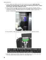
Powder Rinse Cycle
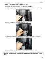
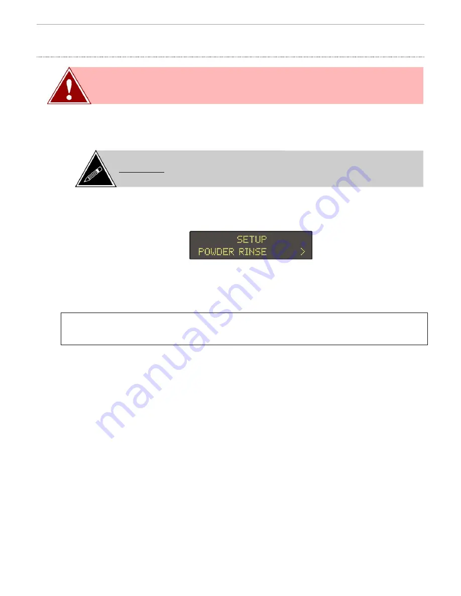
To access the powder rinse cycle,
1.
Enter the Set-Up mode and scroll to the Powder Rinse menu.
2.
Place a large cup or leak-proof container under the dispensing spout.
3.
Press the Enter (
) button to begin the rinse cycle.
4.
Repeat step #3 if more rinsing is required.
NOTE: The Powder System rinse menu automatically appears after the powder hoppers
have been removed, refilled and replaced. Performing this cycle is mandatory and once
it is completed, the machine will automatically revert to Standby (ready) mode.
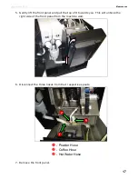
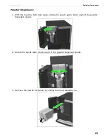
Brewer Rinse
1.
Select the coffee beverage and press the Enter (
) button to open the
brewer.
2.
Instead of inserting a coffee pod into the brewer, insert the special brewer
cleaning tablet into the brewer.
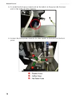
3.
Press the Enter (
) button to activate the vend cycle.
The hot water dissolves the cleaning tablet, which in turn cleans all of the
areas in the brewer system with which it comes into contact.
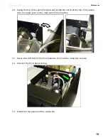
4.
Make several vends afterwards (without inserting anything into the brewer) to
rinse out the cleaning solution.
5.
Make one final vend using a coffee pod to test the brewer.
WARNING: Place a large cup under the dispensing spout area to
catch the water that is dispensed during the rinse cycle.
NOTE: The powder rinse cycle is triggered automatically and is
mandatory after removing and replacing the powder hoppers, or if the
waste bin is removed for more than 10 seconds (default setting).


