background image

GRAPHITE 2

Assembling gide


PURE PLEASURE for YOU 


Technical support:

VLADIMIR'S Model 

http://airplane-model.com

e-mail: 

order@airplane-model.com


GRAPHITE2. Assembling gide 


Technical data: 

Wing span:

 3100 mm 

Wing area:

 64.5 dm 

Length:

 1515mm 

Ready to flight weight ( of the test models): 

Glass version:

 1920 g. 

Carbon:

 2100 g 

F3J extra light version of kevlar:

 1800g 

Wing airfoil:

 MH 32 

Stabilizer airfoil:

 HT14-HT12 

Controlling elements:

 V-form tail, ailerons, flaps


GRAPHITE2

 is designed for experienced pilots. Exceptional quality, computer modeling, careful work 

on aerodynamics, construction designed to combine the extraordinary high strength with minimum weight 
gives you the feeling of pure pleasure. 

This model can be successfully used for different flying types. You can use it as a highest quality glider 
for slope and termic on one hand and as an electric HOTLINER.  

The experience of previous version helped us to get exceptional controllability and flying stability of the 
model at critically low speed (e.g. at the landing). This is possible thanks to the flaps area increase, adding 
of the transversal V angle of the wing central panel and the new V-form tail, designed by Dr. Drella.  

A slight increase of the transversal V angle of the wing allowed to magnify the flying stability and helps 
you to control the model in termic on long distance and also increased the effectiveness of the ruder. 

Extraordinary wind penetration will allow you to return from the far distant thermal. A special 
construction of the fuselage which redistributes loads from the nose to the back part when tough landing 
during the competition. Also, besides the fuselage is strengthened by a layer of unidirectional high 
strength carbon. 

That's why Graphite2 will completely satisfy the experienced pilots ambitions and will surprise the less 
eaperienced pilots with it's stable flying characteristics. 

Summary of Contents for GRAPHITE 2

Page 1: ... as an electric HOTLINER The experience of previous version helped us to get exceptional controllability and flying stability of the model at critically low speed e g at the landing This is possible thanks to the flaps area increase adding of the transversal V angle of the wing central panel and the new V form tail designed by Dr Drella A slight increase of the transversal V angle of the wing allo...

Page 2: ...ILERONS and flaps are completely ready and hinged They also have wipers closing up the slot when aileron flap operates STABILIZER color two section gel coated and laminated in the aluminium mould has sandwich construction and is made of HEREX and fiberglass It has a carbon spar and joiners The elevators are ready and hinged They have wipers closing up the slot ACCESSORIES screws horns clevis metal...

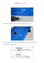
Page 3: ... and stabilizator surfaces when assembling the model and mounting the controlling equipment and regulating the model ATTENTION Any instruments or stiff things may spoil your new model when getting under the surfaces 1 Wing Prepare the wires with connections to install the servos in the wing Use only high quality wires and connectors pic 3 Make a hole in the wing to install the central connector do...

Page 4: ...e pic 4 Make slots for the aileron horns be careful Don t spoil the upper covering pic 5 Insert horn and glue it into the aileron by the cyanoacrylate adhesive as shown at the picture 5 Screw flap horns in deep as possible pic 6 ...

Page 5: ...al units for the Volz Micro Maxx servos mounting or glue them with epoxy If gluing with epoxy pay attention to the moving parts isolation Don t let the glue flow in between the moving and fixed parts of the construction WARNING If your servos can t stand high loads you can face a controlling surfaces flatter which may cause your model crash Use only high quality servos for your model MPX Micro Spe...

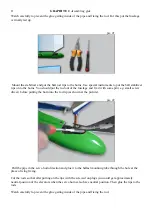
Page 6: ... the plugs are to be screwed to the rods tightly to avoid their free motion Cover the servo well by the servo plate using the double sided tape Work up and glue the small upper well by the cyanoacrylate adhesive pic 9 Tape wing tips before flying ...

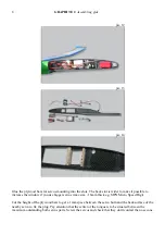
Page 7: ...p Screw in the horns into the holes and fix them together with the balls by the cyanoacrylate adhesive pic 10 Tape stabilizer to fuselage before flying 3 FUSELAGE pic 11 Think over the positions for the servo the receiver and the accumulator in the fuselage attentively or use our recommended positioning ...

Page 8: ...you use bigger servos max size 16mm thick e g MPX Micro Speed Digi Cut the height of the plywood bars to get a 1mm space between the servo horn and the back surface of the nearby servo to fix the plug Pay attention that the center of the tongue is to be situated between the maximum outstanding both servos parts Screw the servos and check that they don t contact the nose cone ...

Page 9: ...de pic 15 pic 16 pic 17 Solder the accumulators in pairs Solder the wire through the tongue and fix the accumulators by the thermo film Glue the accumulators in the thermo film to the tongue by the cyanoacrylate adhesive pic 18 ...

Page 10: ...t into the fuselage Wipe out the extra epoxy Check the tongue gluing depth by putting the nose cone on Put off the nose cone and check if the tongue and fuselage gluing axis coincide Wipe the extra epoxy Fix the tongue with the glue tape untill the epoxy polymerization pic 20 Make a hole in the fuselage to glue the pushrods pipes as shown at the picture Glue the pushrod tip to one side of each rod...

Page 11: ...nd fix it with some pin e g small screw driver before putting the horn into the rod tip as shown at the picture pic 22 Pull the pipe in the servo horn direction and glue it to the ballast mounting tube through the hole at the place of wing fixing Cut the rods so that after putting on the tips with the screwed on plugs you could get approximately neutral position of the elevators when the servo hor...

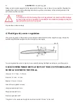
Page 12: ...ll its end to the V form tail Pay attention to this warning 4 Model gravity center regulation The center of gravity of the model is to be situated 110mm back from the wing front edge Choose the needful weight ballast and glue it in the front part of the tongue pic 23 You can regulate the center of gravity more carefully during the flight according to your flying style 5 RECOMMENDED DEVIATION OF TH...

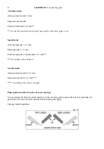
Page 13: ...ards 1 1 5 mm Elevator upwards or downwards 0 5 1 mm According to the situation Termic mode Ailerons downwards 0 5 2 5 mm Flaps downwards 0 5 2 5 mm According to the termic strength Flaps position relatively to the elevators moving You can adjust the flaps deviation relatively to the elevator position upwards but only upwards It s preferable to be able to switch off this function during the flight...

Page 14: ... of gravity if of course you don t want to change the center of gravity position when the model is heavier Fix the ballast by the M3 screw WARNING As carbon is used for the fuselage the receiving antenna is to stand out of the fuselage as close to the receiver as possible You should fix it to outside the fuselage by the glue tape and pull its end to the V form tail Pay attention to this warning Pl...

Reviews: