background image

VMAC - Vehicle Mounted Air Compressors

VMAC Technical Support: 888-241-2289

VMAC Knowledge Base: kb.vmacair.com

49

Ensure any stored air is drained from the system prior to adding oil.


Add oil as necessary to bring the level to the “MAX” line in the sight glass and 

check for leaks.


Start the engine. 


Turn on the compressor and allow it to build to full system pressure. 

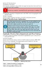
Digital Throttle Auto Calibration

Hydraulic Priority Valve Adjustment and Flow Testing


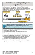
Install a hydraulic flowmeter between the regulated flow port on the priority 

valve, and the crane.


Start the engine.


Set the PTO mode selector switch on the PTO indicator panel to “FIXED RPM”. 


Turn on the compressor. The engine speed should increase to 1,250 rpm.


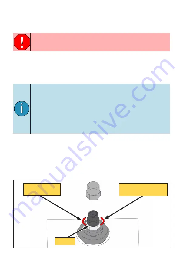
Remove the cover cap (Figure 52).

Figure 52  —  Adjust priority valve

Clockwise to 

reduce flow

Counterclockwise to 

increase flow

Locknut


Turn off the compressor.


Shutdown the engine.


Check the compressor oil level after the engine has been shut down and the oil 

level has had time to stabilize.

The VMAC digital throttle is equipped with an auto calibration and 

engine learning routine that will assist with maintaining accurate 

and stable engine speeds. No user input is required. 
Operators may however notice that while the system is at full 

system pressure and the vehicle is at base VMAC idle, the vehicle 

engine speed may drop by a few hundred rpm and then return to 

normal VMAC base idle as the VMAC digital throttle control auto 

calibrates. This is normal and should only occur once each time the 

system is being operated.

Summary of Contents for DM2A021

Page 1: ...www vmacair com Installation Manual for VMAC Systems DM2A021 DM2B021 DM2C021 2020 Ford Super Duty F250 F600 6 7 L Diesel...

Page 2: ......

Page 3: ...or Tank AOST 21 Hose Requirements 24 Routing and Connecting the Hoses 25 Installing the Air Intake 32 Adding Oil to the System 34 Installing the Control Components 35 Upfitter Vehicle Controls 42 Comp...

Page 4: ...this manual is intended for certified VMAC installers who have been trained in installation and service procedures and or for anyone with mechanical trade certification who has the tools and equipmen...

Page 5: ...e failure of anyone to properly adhere to the procedures set out in this manual or standard safety practices Safety should be the first consideration when performing any service operations If there ar...

Page 6: ...ther products as defined by VMAC provided that i the purchaser fully completes and submits a warranty registration form within 3 months of purchase or 200 hours of operation whichever occurs first ii...

Page 7: ...on the compressor and a detailed description of the work performed 6 VMAC Warranty does not cover consequential damages overtime charges mileage travel time towing recovery cleaning or shop supplies 7...

Page 8: ...e vehicle as many of the OEM parts will be reused during the installation of the VMAC system Read this manual prior to beginning the installation to ensure familiarity with the components and how they...

Page 9: ...on meter N m 54 81 122 244 434 Metric Class 10 9 Size mm M6 M8 M10 M12 M14 M16 Foot pounds ft lb 4 5 19 41 69 104 174 Newton meter N m 6 25 55 93 141 236 Special Tools Required None Torque Specificati...

Page 10: ...upport Disconnect both batteries Apply Loctite 242 blue to all fasteners except nylon lock nuts unless otherwise stated Raise the front of the vehicle and support the axle on axle stands or appropriat...

Page 11: ...or side of the hose measure 5 1 4 in along the outside radius towards the center of the hose and mark with a grease pen Figure 2 Figure 2 Lower radiator hose modification 5 1 4 in To radiator Refer to...

Page 12: ...nter section of the lower radiator hose and slide it over the radiator side coolant tube securing it in place with cable ties Figure 4 Figure 4 Radiator side anti abrasion sleeve Coolant assembly remo...

Page 13: ...r com 11 Mount the cooler to the cooler bracket Figure 6 Figure 7 Install radiator hoses and tube connectors Connect passenger and driver side radiator hoses and tubes to the VMAC cooler Route the ste...

Page 14: ...P N 1710878 short side to cooler Coolant tube P N 1720718 Coolant elbow P N 1710658 Connect the modified OEM hoses as indicated Figure 8 Disconnect the small flexible hose secured to the cable run tra...

Page 15: ...ure the hose is seated against the bead in the OEM hard line and secure using a hose clamp Figure 11 Figure 10 Plug the flexible hose Front of vehicle Plug Flexible hose OEM spring clamp Figure 11 Plu...

Page 16: ...plied P clips bolts and clip nuts secure the heater hose to the radiator support Adjust all connections as necessary to confirm that all joints are engaged securely and that there are no twists kinks...

Page 17: ...o the bracket Remove and discard the bracket from the bellhousing mounting studs Using the OEM fasteners install the supplied bracket onto the bellhousing mounting studs Figure 14 Figure 14 Install su...

Page 18: ...for re alignment later Unbolt the front of the drive shaft pivot it out of the way and secure it to allow room to install the PTO The PTO electrical installation will be covered in Installing the Cont...

Page 19: ...r forward onto the PTO until it is fully mated Figure 16 Figure 16 Install the compressor Using the 2 supplied fasteners and flat washers secure the compressor to the PTO Using a torque wrench ensure...

Page 20: ...unthread the clip from the hole and discard it Position the oil fill bracket over the hole and align the smaller hole with the nearby OEM bolt head Figure 18 Figure 18 Install oil fill bracket OEM fa...

Page 21: ...ear of the compressor gearcase Figure 20 Figure 20 Install alignment guides Apply a generous amount of spline grease supplied with the PTO to both splines Ensure that the grooves of each are fully fil...

Page 22: ...10 ORB Remove the pump and tighten the hydraulic fittings Apply Loctite 242 blue to the supplied fasteners and install the hydraulic pump Refer to the instructions included with the hydraulic pump fo...

Page 23: ...e supplied or recommended by VMAC may cause compressor damage and may void the warranty Figure 23 AOST installed Front of vehicle The AOST must be level for proper air oil separation and to ensure tha...

Page 24: ...d in the frame Using the 2 supplied 3 8 in 6 in bolts install the rear tank mount and backing strap approximately 10 in ahead of the rear cab mount Leave the bolts finger tight to allow for minor adju...

Page 25: ...b vmacair com 23 Rotate the tank so that the directional arrow on the rear of the tank is pointing upwards Figure 25 Figure 25 Securing the AOST Rear view AOST orientation is critical The arrow must b...

Page 26: ...shortened or replaced as necessary or hose extenders can be used VMAC recommends shortening these hoses as a preferred alternative to coiling up and securing the excess Shorter hose length will maximi...

Page 27: ...w for normal engine transmission movement Cut the tube squarely using only proper tubing cutters as side cutters will deform the tube Slide the collet out once the tube is fully inserted Figure 26 Pus...

Page 28: ...spin on oil filter and set it aside Install a cap plug to prevent any contaminants entering the system Install the supplied Tee fitting onto the AOST in the orientation shown Figure 27 Using the suppl...

Page 29: ...it to the Tee on the AOST Connect the 90 fitting from the longer 1 2 in hose cooler to compressor to the passenger side fitting on the oil cooler Connect the 90 fitting from the shorter 1 2 hose AOST...

Page 30: ...ion crossmember Figure 30 Apply the supplied spiral loom to the 3 4 in hose where it runs along the control arm mount and wraps around to the rear of the control arm to provide abrasion protection Usi...

Page 31: ...2 Connect the straight fitting on the 1 2 in hose to the matching fitting on the compressor Figure 32 Apply the supplied spiral loom to the 2 1 2 in hoses where necessary to protect them from abrasion...

Page 32: ...im the PTFE tubes as necessary and connect them to their respective fittings on the back of the AOST Figure 34 Adjust the hoses and or the AOST to minimize sharp bends contact with any hot sharp or mo...

Page 33: ...the priority valve to the input port on the crane Connect the input port on the priority valve to the hydraulic pump Figure 36 Connect priority valve Bypass port return to tank Regulated flow port to...

Page 34: ...the elbow Adjust the rubber elbow and tube assembly to ensure they are routed away from any hot sharp or moving components If required trim any extra length from the hose to allow for the best routing...

Page 35: ...adequately secured away from hot sharp or moving components using rubber coated P clips or cable ties not supplied as required Cut the flexible hose to length and using the supplied gear clamp secure...

Page 36: ...AOST Remove the cap plug used to cover the oil filter port on the AOST Apply a light film of compressor oil to the filter gasket and thread the filter onto the AOST until the gasket makes contact Tig...

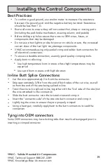
Page 37: ...rical connections To ensure a durable connection use only good quality crimping tools Apply loom to all wiring Use high temperature loom in areas where high temperatures may be expected Use spiral loo...

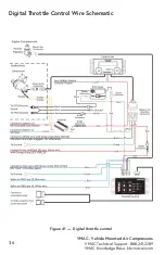
Page 38: ...VMAC Vehicle Mounted Air Compressors VMAC Technical Support 888 241 2289 VMAC Knowledge Base kb vmacair com 36 Figure 41 Digital throttle control Digital Throttle Control Wire Schematic...

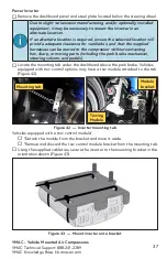
Page 39: ...ter to the mounting bracket in the orientation shown Figure 43 Locate the mounting tab under the dashboard above the park brake Vehicles equipped with tow control options may have a tow module attache...

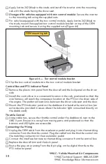
Page 40: ...ient location in the cab positioned so that the wire harness will reach the compressor location at the PTO on the driver side of the engine The preferred location is between the driver side seat and t...

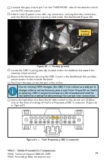
Page 41: ...the control box and the throttle control to a good ground under the dashboard Figure 45 Locate the OBD II port generally located under the dashboard beneath the steering wheel column Remove the fasten...

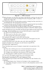
Page 42: ...throttle control Black wire from the white 4 pin connector Red wire from the white 4 pin connector Unplug the SEIC pigtail from the SEIC interface plug Splice the blunt cut red wire from 4 pin connec...

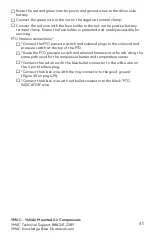
Page 43: ...tected and readily accessible for servicing PTO Harness connections Connect the PTO pressure switch and solenoid plugs to the solenoid and pressure switch at the top of the PTO Route the PTO pressure...

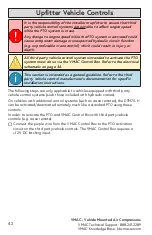
Page 44: ...PTO activation circuit on the third party vehicle controls The VMAC Control Box requires a 12 V DC latching input This section is intended as a general guideline Refer to the third party vehicle contr...

Page 45: ...it up and out of the way under the dash with cable ties Replace all dash panels and covers removed during installation Fill the primary radiator with the saved coolant Connect the batteries To alert a...

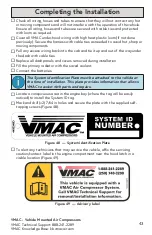
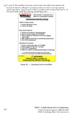
Page 46: ...t of the installation process ensure that the safety and operational instruction decal is affixed in an obvious location so that it can be seen by vehicle operators A good spot for this is usually on...

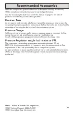
Page 47: ...advantage of lowering the duty cycle of the compressor system Pressure Gauge While not critical to system performance a pressure gauge is important for fine tuning the system and simplifies any poten...

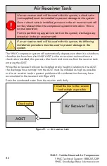
Page 48: ...high as possible Air Receiver Tank AOST Check valve If an air receiver tank will be used with this system the following installation procedure must be used to prevent damage to the system The VMAC co...

Page 49: ...n the control box is still illuminated from the previous step If not ensure the vehicle transmission is in PARK the park brake is applied and the vehicle ignition is turned to ON Cycle the compressor...

Page 50: ...aches full system pressure Engine speed should reduce to between 1 200 rpm to 1 300 rpm Verify that the vehicle coolant level is correct Perform a final inspection of the installation to ensure everyt...

Page 51: ...he engine speed should increase to 1 250 rpm Remove the cover cap Figure 52 Figure 52 Adjust priority valve Clockwise to reduce flow Counterclockwise to increase flow Locknut Turn off the compressor S...

Page 52: ...ol with the appropriate orifice installed for at least 1 2 hour 1 hour preferred Road test the vehicle for approximately 14 miles 20 km Observe the compressor operation to ensure that the belt alignme...

Page 53: ...mately 2 400 rpm Close the air valve slowly to allow the system pressure to rise Once system pressure is at maximum slowly open the ball valve on the test tool until the pressure on the gauge begins t...

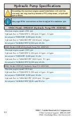
Page 54: ...VARIABLE RPM 2 500 rpm 6 8 gpm Air output in VARIABLE RPM 2 500 rpm 65 cfm VMAC Model DM2B021 Hydraulic Pump P N 4500163 Maximum engine speed 2 300 rpm Hydraulic flow in FIXED RPM 1 250 rpm 4 3 gpm 6...

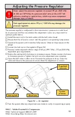
Page 55: ...psi 1205 kPa dependent upon requirements Rotate the setting bolt clockwise to increase pressure Rotate counter clockwise to decrease pressure Tighten the lock nut once adjustments are complete Open th...

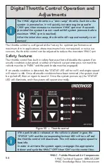
Page 56: ...ce the maximum VMAC rpm Safety features The throttle control has built in safety features that will disable the system if an unsafe condition is detected or either of the lock out parameters is not me...

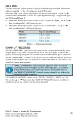
Page 57: ...aximum VMAC rpm can be adjusted in 50 rpm increments via the or buttons in the MAX RPM column The rpm adjustment range is dependent upon the DTM model Table 2 When the PTO mode selector switch is set...

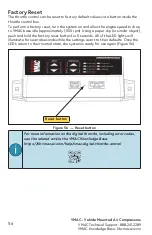
Page 58: ...ase idle approximately 1 000 rpm Using a paper clip or similar object push and hold the factory reset button for 5 seconds All of the LED lights will illuminate for several seconds while the settings...

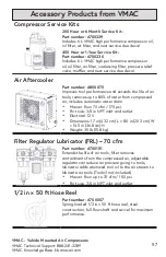
Page 59: ...ll flow shaft and swivel for maximum performance Accessory Products from VMAC Air Aftercooler Part number A800070 Improves tool performance and extends the life of air tools removes up to 80 of water...

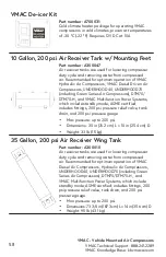
Page 60: ...ons 73 3 4 in 187 3 cm L 14 in 35 6 cm D Weight 95 lb 43 1 kg 10 Gallon 200 psi Air Receiver Tank w Mounting Feet Part number A300047 Air receiver tanks are used for lowering compressor duty cycle and...

Page 61: ...VMAC Vehicle Mounted Air Compressors VMAC Technical Support 888 241 2289 VMAC Knowledge Base kb vmacair com 59...

Page 62: ...VMAC Vehicle Mounted Air Compressors VMAC Technical Support 888 241 2289 VMAC Knowledge Base kb vmacair com 60 Notes...

Page 63: ...VMAC Vehicle Mounted Air Compressors VMAC Technical Support 888 241 2289 VMAC Knowledge Base kb vmacair com 61 Notes...

Page 64: ...VMAC Vehicle Mounted Air Compressors VMAC Technical Support 888 241 2289 VMAC Knowledge Base kb vmacair com 62 Notes...

Page 65: ...VMAC Vehicle Mounted Air Compressors VMAC Technical Support 888 241 2289 VMAC Knowledge Base kb vmacair com 63 Notes...

Page 66: ...y VMAC within 3 months of receiving the vehicle or 200 hours of operation whichever occurs first VMAC s Warranty policy and registration can be viewed online at www vmacair com warranty Warranty Regis...

Page 67: ......

Page 68: ...888 241 2289 tech vmacair com 877 740 3202 warranty vmacair com www vmacair com kb vmacair com 1333 Kipp Road Nanaimo B C V9X 1R3 Canada Manufactured by...

Reviews: