background image

VMAC – Vehicle Mounted Air Compressors


Toll Free:


1-800-738-8622 Local: 1-250-740-3200 

Fax: 1-250-740-3201 

29

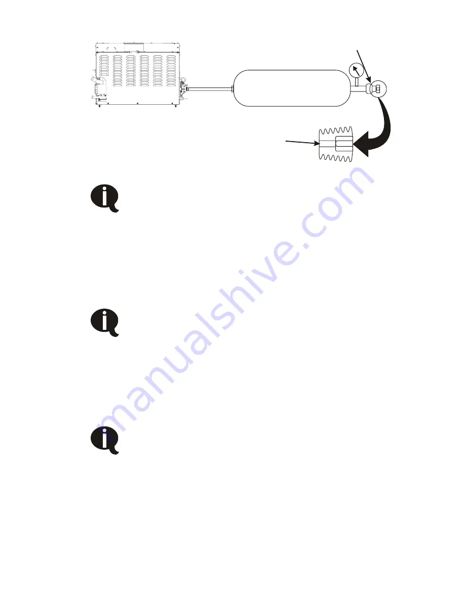
Compressor

Air receiver

Ball valve

Orifice drilled in plug

Pressure gauge


Figure 19 – Test setup 


If the air pressure drops below 100 psi, increase 
hydraulic flow to bring the pressure back up. Do not 
exceed hydraulic flow specifications 

9.  Test the system for 1 hour at the maximum duty cycle. Make 

sure that you can read the temperature for the duration of the 
test without disturbing the system by opening cabinets or other 
functions. 

10. Record “T

2

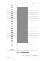
” every 30 seconds during the last 10 minutes of the 

test.  Record “T

1

” at the 50 minute and 60 minute marks. 


Copy and use Form 2 on the following page for your 
calculations. 
 

11.  For the analysis, “T

1

” is the average of the two “T

1

” readings and 

“T

2

” is the average of the 20 “T2” readings taken in step 10.  “T

3

” 

is the maximum ambient temperature to which the vehicle will be 
exposed. 


If the system shuts down at any point during the test, 
check the LEDs on the the top of the unit for Flash 
Codes and cross-reference them to the table in the 
Owner’s Manual. If the system shut down due to and 
over-temperature condition, check all oil levels, improve 
ventilation and repeat the test once the system has 
cooled. 


Summary of Contents for PREDATAIR60

Page 1: ...ing the PREDATAIR60 15 3 1 Mounting the Compressor 15 3 2 Connecting the Wiring 15 3 3 Speed Control 20 4 0 Completing the Installation 23 4 1 Before Operation Checklist 23 4 2 After Engaging the Hydr...
Page 2: ...llation if you do not have the appropriate mechanical training knowledge and experience Follow all safety precautions for mechanical work If you have difficulty with the installation contact VMAC The...

Page 3: ...nical separation The second stage uses a special separation element which delivers dry air to the outlet Pressure regulation is achieved with a mechanical inlet control valve and an adjustable pressur...

Page 4: ...ith check valve Hydraulic fluid inlet Hydraulic fluid return Blowdown cap with internal coalescing filter Minimum clearance for servicing 6 inches Compressor oil fill shipped full from the factory Oil...

Page 5: ...VMAC Vehicle Mounted Air Compressors Toll Free 1 800 738 8622 Local 1 250 740 3200 Fax 1 250 740 3201 5 Figure 2 System wiring...

Page 6: ...sily without having to disconnect lines or remove and reposition the unit it will be protected from excessive exposure to the elements and possible incidental damage from other operations it is away f...

Page 7: ...is not possible to make absolute recommendations regarding ventilation because of the widely differing circumstances that are possible Duty cycle ambient temperature and enclosure shape are some of th...

Page 8: ...250 740 3200 Fax 1 250 740 3201 8 Figure 4 Ideal ventilation with ambient air vent of a suitable size for the application Avoid installing deep into enclosures that will not permit adequate air circu...

Page 9: ...gure 6 Top view Hot air recirculating Top view Dams installed to block recirculation Figure 6 Reducing hot air recirculation Recommended minimum clearances if no back ventilation is possible are very...

Page 10: ...VMAC Vehicle Mounted Air Compressors Toll Free 1 800 738 8622 Local 1 250 740 3200 Fax 1 250 740 3201 10 6 6 6 6 Figure 7 Minimum clearances...

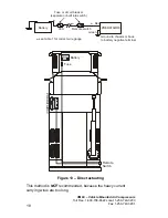
Page 11: ...ate when the door is open Figure 9 Battery Relay PREDATAIR60 Remote switch Door switch Figure 9 Door switch 2 2 Hydraulic Requirements If the compressor is being installed on a truck that does not hav...

Page 12: ...this manual is based on a fixed displacement pump Special considerations may be required for a variable displacement pump 2 3 Electrical Requirements The PREDATAIR60 requires a steady 17 Amps 12 VDC...

Page 13: ...Air Receiver Requirements The PREDATAIR60 uses an unloader system which minimizes fuel burn equipment wear cooling load enclosure temperature hydraulic temperature and noise when compressed air is no...

Page 14: ...REDATAIR60 Tank Auxiliary Tank One way check valve built into PREDATAIR60 tank Install this line high on the tank not at the bottom Figure 10 Auxiliary tank connection A one way check valve is built i...

Page 15: ...ur 11 32 inch holes in the selected mounting location spaced at 22 inches wide and 14 inches deep Fasten the unit in place using Loctite on the threads A mounting bracket kit A700140 is available Do n...

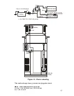
Page 16: ...16 Battery Fuse Relay Remote Switch PREDATAIR60 Battery Fuse or circuit breaker 30A Relay PREDATAIR60 Remote switch see table 1 for correct wire gauge 18 AWG Ground to chassis or back to battery negat...

Page 17: ...Battery Fuse Relay Remote Switch PREDATAIR60 Battery Fuse or circuit breaker 30A Relay PREDATAIR60 Remote switch see table1 for correct wire gauge 18 AWG 18 AWG Ground to chassis or back to battery ne...

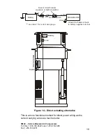
Page 18: ...Switch PREDATAIR60 Battery Fuse or circuit breaker separate or built into switch 30A PREDATAIR60 Remote switch see table 1 for correct wire gauge Ground to chassis or back to battery negative termina...

Page 19: ...Battery Fuse or circuit breaker separate or built into switch 30A PREDATAIR60 Remote switch see table 1 for correct wire gauge Ground to chassis or back to battery negative terminal Red Green Figure...

Page 20: ...er wear rate on engine hydraulic pump and compressor greater latitude for flexible service intervals better cold start behavior The preferred approach for speed control is to keep the hydraulic flow a...

Page 21: ...cuit is switched on Speed 1 Set speed 1 to achieve desired CFM not connected Figure 15 Single speed operation Two Speed There are two options for two speed operation Speed 1 This is typically set for...

Page 22: ...22 Red Purple Green From PREDATAIR60 activation circuit Throttle control 12V input when activation circuit is switched on and the purple wire is grounded by the control system Speed 1 Speed 2 Set Spe...

Page 23: ...Engaging the Hydraulics Checklist Place the truck in a safe operating position and block the wheels Ensure that there are no people around the truck before beginning the test Make sure that the follow...

Page 24: ...t tool 1 Install the test tool in the tank outlet fitting 2 Make sure that the ball valve is closed 3 Place the manual transmission in neutral or the automatic transmission in park and fully apply the...

Page 25: ...Fax 1 250 740 3201 25 8 Close the ball valve to allow the system pressure to rise When the control system does not sense air use for a few seconds it will unload the compressor You should hear a hiss...

Page 26: ...based on a 25 duty cycle For example a 1 2 impact might be listed by the manufacturer as 5 CFM rather than the true consumption of 20 CFM Do not use the average rating in calculating duty cycle Typica...

Page 27: ...t per Hour 460 Duty Cycle Total CFH 3600 x 100 460 3600 x 100 13 Table 2 Sample calculation Use Table 3 to find the orifice size and expected CFM based on the calculated duty cycle Duty Cycle Orifice...

Page 28: ...to 10 feet away from the vehicle this is ambient temperature T1 3 Temporarily mount a second thermometer Figure 18 2 inches away from where the air will enter the cooler T2 2 Thermometer T2 Figure 18...

Page 29: ...r other functions 10 Record T2 every 30 seconds during the last 10 minutes of the test Record T1 at the 50 minute and 60 minute marks Copy and use Form 2 on the following page for your calculations 11...

Page 30: ...1 800 738 8622 Local 1 250 740 3200 Fax 1 250 740 3201 30 Time min sec T1 T2 50 00 50 30 51 00 51 30 52 00 52 30 53 00 53 30 54 00 54 30 55 00 55 30 56 00 56 30 57 00 57 30 58 00 58 30 59 00 59 30 60...

Page 31: ...ient temperature that the truck will see Duty Cycle _______ See Section 5 1 No of speeds 1 or 2 Circle one Tmax _______ See Table 4 Tx T3 T2 T1 The expected cooler intake temperature at maximum ambien...

Page 32: ...7 C 90 89 F 32 C 89 F 32 C 100 85 F 29 C 85 F 29 C Table 4 Determining Temperature TMAX Table 5 shows a sample analysis using Form 3 Measures for correcting inadequate ventilation include reduce GPM a...

Page 33: ...ne Tmax 151F See Table 4 Tx T3 T2 T1 The expected cooler intake temperature at maximum ambient temperature Tx _100_ _124_ _58_ _166F_ Tmax _151F_ Tx _166F_ If Tmax is greater than or equal to Tx the v...

Page 34: ...ressor filling receiving tank cold hydraulic fluid 3 Compressor unloading 4 No air consumption compressor in unloaded state 5 Brief use of compressed air compressor tops up receiver and unloads 6 No a...

Page 35: ...ystem design guidelines generally call for the following maximum fluid velocities which are then used to select line sizes for any particular GPM suction 4 ft sec return 10 ft sec pressure 20 ft sec F...

Page 36: ...s that will provide sufficient oil flow to the pump during startup with cold oil The system should be designed to run at the lowest GPM possible at startup then use a throttle control to increase GPM...

Page 37: ...1 5 ft 2 up to 3 ft 2 1 2 up to 8 ft 3 above 8 ft Table 9 Cold Climate GPM during pump start up and warm up Suction hose size AW 32oil Suction hose size AW 46 oil 8 GPM 1 up to 4 ft 1 1 4 up to 8 ft...

Page 38: ...om Table 4 cold climate 12 GPM AW32 1 1 2 is good up to 4 40 For 4 tank level 5 6 1 3 4 is good up to 6 40 8 4 conclusion use 1 3 4 ID suction hose or larger 6 2 2 Return Line Sizing Choose a return l...

Page 39: ...Return line size 8 GPM 1 up to 3 ft 1 1 4 up to 8 ft 1 1 2 above 8 ft 12 GPM 1 up to 2 ft 1 1 4 up to 5 ft 1 1 2 up to 12 ft 1 3 4 above 12 ft 16 GPM 1 1 4 up to 4 ft 1 1 2 up to 9 ft 1 3 4 above 9 ft...

Page 40: ...up to 12ft 1 1 4 above 12ft Extreme Cold Climate With Tank and Suction line preheat AW32 oil Pressure line not preheated 20 3 4 up to 3ft 1 up to 9ft 1 1 4 above 9ft Table 14 6 3 Hydraulic System Fil...

Page 41: ...l level is well above suction line opening avoiding the possibility of drawing air into the pump due to a vortex or whirlpool effect more forgiving towards unusual vehicle attitudes to keep return flo...

Page 42: ...o facilitate draining of old hydraulic oil during service should be at the lowest point in the reservoir to assure complete draining It should be installed using an adaptor or housing which does not p...

Page 43: ...nd should be easily accessed for cleaning A temperature gauge either separate or built into the sight glass allows operator to read reservoir oil temperature A strainer in the filler neck keeps large...

Page 44: ...raulic system performance Some steps to take to avoid pump cavitation Mount the hydraulic oil tank as high above the pump as possible Keep the suction line as short as possible Avoid sharp 90 degree b...

Page 45: ...s Reduces pressure for longer tool life Hose Reel Secure compact retractable hose storage in a sturdy reel Air Receiver Tank Thirty five gallon capacity in a compact tank complete with fittings and a...

Reviews: