background image


VMAC 

– Vehicle Mounted Air Compressors


Toll Free:


1-888-241-2289 

Fax: 1-250-740-3201 

84 

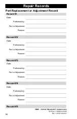
Repair Records 

Part Replacement or Adjustment Record 

Record #1 

Date: 


Performed by:   

Part or Adjustment:   

Reason:   


Record #2 

Date: 


Performed by:   

Part or Adjustment:   

Reason:   


Record #3 

Date: 


Performed by:   

Part or Adjustment:   

Reason:   


Record #4 

Date: 


Performed by:   

Part or Adjustment:   

Reason:   


Record #5 

Summary of Contents for RAPTAIR-G30

Page 1: ...RAPTAIR G30 Gas Drive Air Compressor Installation Owner s and Service Manual G300002...

Page 2: ......

Page 3: ...lation Requirements 20 Mounting Locations 21 Mounting the Compressor 22 System Hoses 25 Electrical Connections 26 Before Starting the Gas Drive 27 Starting and Stopping the Gas Drive 28 Setup Performa...

Page 4: ...ct to change without notice Registered Trademarks All trademarks mentioned in this manual are the property of their respective owners Their use by VMAC is for identification of the manufacturers produ...

Page 5: ...d Lifetime Warranty The Compressor Assembly excluding Inlet and Clutch where applicable is warranted against manufacturer defects in materials and workmanship for the lifetime of the Compressor Assemb...

Page 6: ...here to the procedures set out in this manual or standard safety practices Safety should be the first consideration when performing service operations If you have any questions concerning the procedur...

Page 7: ...e death Do not start or operate this compressor in an enclosed area Always use the appropriate personal protective equipment particularly eye and hearing protection when operating air powered equipmen...

Page 8: ...parate suddenly fly out and cause serious injury or death If equipped the receiver air tank must be drained before servicing any components in the compressor system Never adjust or attempt to make any...

Page 9: ...ug wire before attempting any repair or service Be attentive for unexplained changes in operation parameters and record any changes Check compressor oil level and condition before starting the system...

Page 10: ...eme hazard Stay clear of all moving parts when the system is operating Only qualified personnel should perform maintenance and repair on system components and only while the system is properly shut do...

Page 11: ...own valve to discharge system pressure on shut down Temperature safety switch in compressor oil cooler A 15A fuse protects the electrical system Figure 1 Safety components Shroud removed for clarity A...

Page 12: ...ure is cooled the majority of the oil separates from the air first stage separation and settles into the reservoir tank below the cooler The cooled oil then passes through a high pressure oil filter b...

Page 13: ...uired Pressure Regulation Pressure regulation is achieved with a mechanical unloader valve and discharge valve Use a Filter Regulator Lubricator FRL to set the final tool pressure System Pressure Unlo...

Page 14: ...e pull choke in cold environments or for first start of the engine Compressor system components must all be at or above 0 C 32 F Starting the system while any of the components are below 0 C 32 F may...

Page 15: ...key switch is in the run position If the gas drive shuts off due to overheat allow the system to cool before restarting For engine oil recommendations in temperatures above 35 C 90 F refer to the Sub...

Page 16: ...compressor output and may cause the engine to stall For operation above 2500 feet lowering the compressor air pressure to 100 psi is recommended For further information please contact VMAC Technical...

Page 17: ...d near the top of the belt guard Please have this number ready when ordering parts or when calling in for technical support Figure 3 Figure 3 Serial number plate and location Support and Parts To orde...

Page 18: ...verview The compressor is directly driven by a belt anytime the engine is running the compressor is running System Components WHASP tank Waste Heat Air Separation Package Rotary Screw Compressor Contr...

Page 19: ...rol panel that features an hour meter key switch and choke The hour meter and fan will be running when the key is in the Run position whether the engine is running or not There are two options for the...

Page 20: ...engine Automatic idle idles up and down based on air demand Automatic system pressure unload with manual override Hour meter runs anytime the key switch is on Electric cooling fan runs anytime the key...

Page 21: ...Engine oil drain oil fill fuel fill and air filter can be easily accessed for service Sufficient clearance around the unit for good air circulation and effective cooling Mounted in a position where ho...

Page 22: ...n the Gas Drive is air cooled special attention must be taken to ensure adequate air flow to the engine Ensure there is a minimum of 6 in 150mm clearance between engine air intake recoil starter area...

Page 23: ...t the escape of hot air from around the unit and have an adverse effect on cooling Make sure that adequate ventilation is provided so the cooling system will function properly VMAC recommends mounting...

Page 24: ...01 22 Mounting the Compressor External dimensions with the base plate Locate a suitable mounting position for the Gas Drive Place the unit and check for clearances to any other objects Figure 11 All d...

Page 25: ...are required Figure 12 Drill four holes in the mounting surface and secure the Gas Drive to the vehicle Use a minimum of four 3 8 in 10 mm bolts Use bolts washers and locknuts or Loctite Remove the 8...

Page 26: ...h can be used as mounting bolt locations Figure 13 Drill 4 holes in mounting surface and secure the Gas Drive engine and WHASP tank to the vehicle Use bolts washers and locknuts or Loctite Remove the...

Page 27: ...d with this system 300 F temperature rating There are two different types of hoses used with the Gas Drive compressor Braided oil hoses VMAC braided hoses have an AQP elastomer liner for compatibility...

Page 28: ...s cable length total length of power wire plus ground wire Suggested Gauge Less than 5 ft 1 5 m 4 AWG 5 ft 1 5 m to 8 ft 2 5 m 2 AWG 8 ft 2 5 m to 13 ft 4 5 m 1 AWG Table 2 Battery extension gauge Key...

Page 29: ...l inspection to ensure that all fasteners and connections are tight 6 Check that all hoses and wiring are secure and adequately protected 7 Check for any fluid leaks around the unit 8 Ensure the fuel...

Page 30: ...perature is below 0 C the unloader valve can be opened to reduce load on the engine while it warms up Pull out or rotate the handle to unload the compressor release tension to load the compressor and...

Page 31: ...not operate the electric starter continuously for more than 5 seconds even if the engine does not start If the engine fails to start wait 10 seconds before trying to restart 3 Once running push the ch...

Page 32: ...ve with the Pull Start 1 Turn the key switch to the RUN position Figure 21 Figure 21 Key switch 2 Pull the choke to the ON position Figure 22 Figure 22 Choke 3 Pull the recoil starter handle gently un...

Page 33: ...88 241 2289 Fax 1 250 740 3201 31 out the cord all of the way Once the engine has started gently return the handle to its original position Figure 23 Figure 23 Recoil starter 4 Once running push the c...

Page 34: ...ool 2 Allow the system to build to full air pressure factory setting 150 psi so that the intake valve in the compressor inlet valve closes At this point the engine will idle down 3 Allow the engine to...

Page 35: ...ings Hose reels etc should be temporarily disconnected and the test tool connected directly to the outlet of the receiver tank Long and or undersized air lines will result in loss of performance 2 Ens...

Page 36: ...pm will decrease the cfm output and may cause the engine to stall Raising the engine rpm may damage the engine The engine low idle and high idle screws are set at the factory and do not require adjust...

Page 37: ...ents For information on installing a receiver tank see the Air Receiver Tank section of this manual Receiver tanks are available for purchase through VMAC See the Accessory Product page of this manual...

Page 38: ...ng the engine speed and producing air It also has the advantage of lowering the duty cycle of the compressor system If the plumbing downstream from the Gas Drive has no leaks a 6 gallon air receiver t...

Page 39: ...meter choke and unloader valve Low Profile Air Receiver Tanks Part number A500037 A500183 Dual 6 gallon air receiver tanks with G30 mounting frame that includes gauge fittings hose drain and pressure...

Page 40: ...air filter 400 Hour Part number A700220 Includes compressor oil oil filter air filter blow down muffler and pressure relief valve Engine Service Kit Part number A500039 100 hour engine service kit in...

Page 41: ...filter body with cyclone pre filter compressor adapter and flexible intake hose Test Tool Part number A700052 Tool to test the output of VMAC air compressor systems comes with adapter fittings hose 2...

Page 42: ...t operated on a regular basis impact damage and premature bearing failure may occur in the compressor due to vibrations from the vehicle Operate the system with no air usage closed system at least onc...

Page 43: ...tery and spark plug wire must be disconnected before attempting any repair or service Turning the crankshaft may cause the engine to start and cause serious injury 4 Disconnect the negative battery te...

Page 44: ...e appropriate personal protective equipment particularly gloves and eye protection 9 Wash skin with soap and clean water after performing repair or service Compressor and engine oil may cause skin irr...

Page 45: ...f engine oil Check hoses and tubes for damage or wear Inspect drive belt Inspect blow down muffler Every 6 months or 200 hours as shown on the hour meter Change compressor oil Change compressor oil fi...

Page 46: ...system Overfilling the system with oil can flood the sight glass window make the system appear empty and may cause oil to come out of the blow down muffler or oil to carry over 1 Ensure the vehicle i...

Page 47: ...physical damage replace component If the damage indicates possible misalignment check pulley alignment If the pulleys are not properly aligned check all fasteners to ensure that they are properly tor...

Page 48: ...dence of corrosion or loss of functionality Ensure the muffler allows the blow down to depressurize the system To test the blow down system and muffler 1 Turn the system on and have it reach operating...

Page 49: ...first Inspect the pressure relief valve for signs of corrosion or loss of functionality To test the pressure relief valve functionality 1 Visually inspect the valve and ensure it is not corroded and...

Page 50: ...retaining screw rotate counter clockwise the filter cover and the filter element 3 Immediately cover the compressor opening by masking with tape or with a clean cloth to prevent contamination Do not u...

Page 51: ...nding system pressure Never over tighten the filter as this may damage the seal or the filter Ensure the new filter is a genuine VMAC filter part number 9200039 This oil filter is a high pressure oil...

Page 52: ...remove it carefully to avoid thread damage coat the threads that go into Separator Tank Base with a small amount of blue Loctite and install it into the Tank Base Figure 37 Figure 37 Compressor oil fi...

Page 53: ...age to the compressor and will void the warranty Overfilling the compressor oil may cause oil to come out of the blow down muffler or into the discharge air stream 1 Clean the area around the tank and...

Page 54: ...Do not overfill the system Overfilling the system with oil can flood the sight glass window and make the system appear empty and may cause oil to come out of the blow down muffler or oil to carry ove...

Page 55: ...ange the coalescing filter 1 Clean the tank in the area of the coalescing filter to prevent contamination 2 Remove the spin on type coalescing filter by turning it counterclockwise 3 Check the gasket...

Page 56: ...ours Change engine oil Change spark plug Change air filter VMAC sells a 100 hour engine tune up kit Part number A500039 See Table 7 for contents Description Part Number Quantity Engine oil 10W30 1L 54...

Page 57: ...entering the engine 2 Undo the two latches on the air filter box remove the filter cover and the filter element 3 Immediately cover the engine filter opening by masking with tape or with a clean cloth...

Page 58: ...quipped with optional oil drain extension 2 Clean the area around the drain plug to prevent contamination 3 Remove the plug to drain the oil into a container large enough to hold at least 1 US Gallons...

Page 59: ...uld involve the following Accurately identifying the problem by operating the system following safety practices Determining possible causes for the problem by understanding how the system operates Iso...

Page 60: ...lief valve Replace pressure relief valve SYMPTOM POSSIBLE CAUSE CORRECTIVE ACTION Compressor will not build to set pressure Verified by pressure gauge Pressure relief valve leaking Replace pressure re...

Page 61: ...bration Loose fasteners Torque fasteners use appropriate thread locking compound Belt or pulley worn Replace components as needed SYMPTOM POSSIBLE CAUSE CORRECTIVE ACTION Engine does not decrease idle...

Page 62: ...equipment on level ground Operating angle in excess of 15 degrees from horizontal Reduce operating angle Incorrect start up shut down procedures Observe start up shut down procedures detailed in this...

Page 63: ...engine Add fuel to engine Spark plug gap Replace spark plug Engine air intake restricted Remove restriction replace air filter Engine exhaust system plugged or restricted Clean or replace exhaust spa...

Page 64: ...he gas drive the purpose of this orifice is to simulate a tool operating at 30 cfm Do not run the system without an orifice Figure 44 Figure 44 A700052 Test Tool PTFE test tool Construct a test tool w...

Page 65: ...cated on the VMAC test tool gauge reaches 150 psi the gauge connected to the1 4 in PTFE tube should read 150 psi If the pressure on the gauge connected to the1 4 in PTFE tube does not rise confirm the...

Page 66: ...2289 Fax 1 250 740 3201 64 To better familiarize yourself with compressor components completely read through this section of the manual Figure 46 Test equipment installed Air Receiver Tank not shown...

Page 67: ...provides the system air pressure factory setting 150 psi to operate the unloader valve and discharge valve inlet poppet valve and throttle actuator Figure 48 Scavenge Tube A 1 4 in PTFE tube shown in...

Page 68: ...removed for clarity Throttle Control The engine rpm is controlled by the throttle actuator which is operated by an air pressure signal from the unloader valve As the unloader valve activates and send...

Page 69: ...the compressor inlet poppet valve If the poppet valve is open the compressor will build air pressure Figure 51 Figure 51 Poppet valve open If the poppet valve is closed the compressor will not build a...

Page 70: ...ill not be solved by a higher fuse rating Exceeding the rating can cause component damage Figure 53 Electrical schematic Electrical Components Over temperature switch Over temperature relay Electric F...

Page 71: ...he thermostatic switch will disable the engine ignition system but the cooling fan will remain running as long as the key switch is in the On position Figure 54 Temperature switch location The engine...

Page 72: ...n 1 Disconnect the fan electrical connector 2 Use a multimeter to measure the resistance through the fan the reading should be around 1 4 3 With the key switch on the blue wire should have battery vol...

Page 73: ...g or starting the engine starter will still function Relay Pin Connections 30 Ground 87A Ignition will be an open circuit with the key switch in the run position and will be grounded with key switch i...

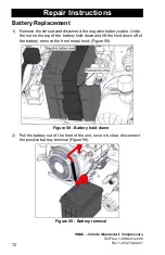
Page 74: ...d and disconnect the negative battery cable Undo the nut on the top of the battery hold down and lift the hold down off of the battery remove the front metal hook Figure 58 Figure 58 Battery hold down...

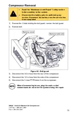
Page 75: ...connect the battery once the service has been completed 1 Remove the 5 bolts holding the belt guard remove the belt guard 2 Remove belt Figure 60 Belt guard 3 Disconnect the 3 4 in hose from the rear...

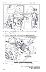
Page 76: ...from the side of the compressor Figure 61 Figure 61 Compressor side bolt 7 Remove center bolt from the compressor pulley and remove the pulley Figure 62 8 Remove 4 compressor bolts from the belt guar...

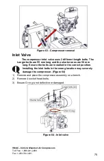
Page 77: ...h bolts The Longer bolts are 55 mm long and the shorter ones are 50 mm long Ensure the bolts are installed in the correct position Installing the inlet bolts in the wrong location may severely damage...

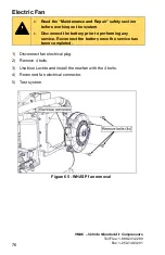
Page 78: ...ection before working on the system Disconnect the battery prior to performing any service Reconnect the battery once the service has been completed 1 Disconnect fan electrical plug 2 Remove 4 bolts 3...

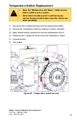
Page 79: ...prior to performing any service Reconnect the battery once the service has been completed 1 Disconnect the 2 spade terminals from the temperature switch 2 Remove the temperature switch by rotating it...

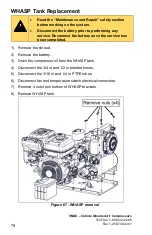
Page 80: ...erforming any service Reconnect the battery once the service has been completed 1 Remove the shroud 2 Remove the battery 3 Drain the compressor oil from the WHASP tank 4 Disconnect the 3 4 in and 1 2...

Page 81: ...r must be serviced as per manufacturer s specifications for the warranty to be considered valid Maintenance and Repair Records System Installation System ID number Compressor Serial Number System Inst...

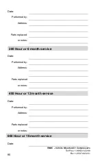
Page 82: ...Fax 1 250 740 3201 80 Date Performed by Address Parts replaced or notes 200 Hour or 6 month service Date Performed by Address Parts replaced or notes 400 Hour or 12 month service Date Performed by Add...

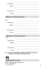
Page 83: ...Parts replaced or notes 800 Hour or 24 month service Date Performed by Address Parts replaced or notes 1000 Hour or 30 month service Date Performed by Address Parts replaced or notes See note in the S...

Page 84: ...9 Fax 1 250 740 3201 82 Date Hours Performed by Address Parts replaced or notes Additional service log Date Hours Performed by Address Parts replaced or notes Additional service log Date Hours Perform...

Page 85: ...888 241 2289 Fax 1 250 740 3201 83 Date Hours Performed by Address Parts replaced or notes Additional service log Date Hours Performed by Address Parts replaced or notes Additional service log Date Ho...

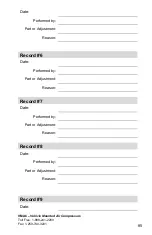
Page 86: ...1 84 Repair Records Part Replacement or Adjustment Record Record 1 Date Performed by Part or Adjustment Reason Record 2 Date Performed by Part or Adjustment Reason Record 3 Date Performed by Part or A...

Page 87: ...88 241 2289 Fax 1 250 740 3201 85 Date Performed by Part or Adjustment Reason Record 6 Date Performed by Part or Adjustment Reason Record 7 Date Performed by Part or Adjustment Reason Record 8 Date Pe...

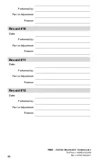
Page 88: ...Free 1 888 241 2289 Fax 1 250 740 3201 86 Performed by Part or Adjustment Reason Record 10 Date Performed by Part or Adjustment Reason Record 11 Date Performed by Part or Adjustment Reason Record 12 D...

Page 89: ...This page intentionally left blank...

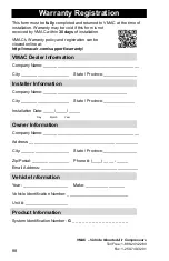
Page 90: ...Installer Information Company Name _____________________________________ City _____________________ State Province ______________ Installation Date _____ _____ _____ Day Month Year Owner Information C...

Page 91: ...This page intentionally left blank...

Page 92: ...This page intentionally left blank...

Page 93: ...This page intentionally left blank...

Page 94: ...This page intentionally left blank...

Page 95: ......

Page 96: ......

Reviews: