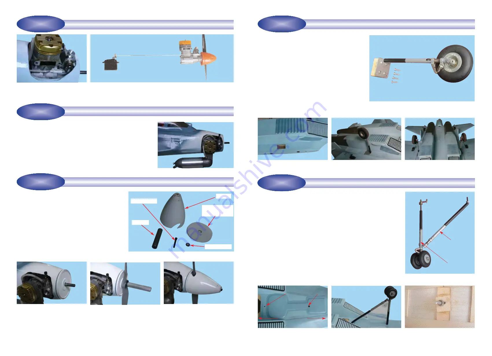
Step 8.1
Invert the fuselage and locate the pre-drilled main
landing gear mounting cavities on the bottom of the fuse-
lage. See 8B.
Step 8.2
Insert one of the pre-assembled main landing
gear into place. Use 4 sheet metal screws to attach the
landing gear to the fuselage. See 8C.
Step 8.3
Repeat step 8.2 to attach the second main land-
ing gear to the fuselage.
Step 15.1
Consult your engine manual and select a suit-
able propeller. See 15A
Step 15.2
Install the thrust washer, the spinner backing
plate, the propeller, the prop washer, and the prop nut sup-
plied with the spinner. Ensure that they are all firmly
attached. See 15B, 15C
Step 15.3
Trial fit the spinner cone and spinner cone
retaining screw. If necessary enlarge the cutouts in the
spinner cone to allow adequate clearance for the propeller.
See 15D
Step 15.4
Double check that the spinner cone retaining
screws are firmly attached.
Step 9.1
Review illustrations 9A, 9B and 9C then insert the front nose gear oleo
strut and support strut into the mounting holes in the bottom of the fuselage.
Step 9.2
Use the 4mm collar with set screw to secure the support strut in place.
See 9D.
Step 9.3
After securing the support strut into place, carefully pull the oleo strut
back out of its fuselage hole. See 9E. Do not detach the support strut
.
Step 9.4
Working inside the fuselage, pass the nose gear steering rod through
the EZ connector attached to the steering arm. See 9F. Do not tighten the steer-
ing arm set screw yet.
Step 9.5
Working from outside the fuselage carefully re-insert the oleo strut
back into its fuselage hole and then from inside the fuselage pass the oleo wire
through the steering arm. See 9G. Tighten the steering arm set screw.
7
8A - Components of one main landing gear with oleo strut.
INSTALLING THE MAIN LANDING GEAR
STAGE 8
INSTALLING THE NOSE GEAR
8B - Main landing gear location on
the fuselage (left side)
8C - Mount the main landing gear to
the fuselage.
8D - Both main landing gear mounted
to the fuselage.
15B - Install the spinner backing plate
15C - Install the propeller, the prop
washer and the prop nut
15D - Install the spinner cone using
the retaining bolt. Ensure the retain-
ing bolt is tight and secure
9B - Turn over the fuselage & locate
the mounting holes for the oleo strut
and the support strut.
9C -
Insert the front nose gear oleo
strut and the support strut.
9D - Use the 4mm collar and set screw
to secure the support strut.
9A - Oleo nose gear & strut assembly
Identify the nose gear components per illustration 9A
- 1 completed oleo nose gear assembly with strut, strut support and wheels
- 1 steering arm with pre-installed EZ-connector
- 1 collar (4mm)
10
15A - Aluminum spinner complete with all hardware (sup-
plied)
INSTALL THE PROPELLER AND THE SPINNER
STAGE 15
Identify the main landing gear components shown below:
- 2 pre-bent oleo main landing gear sets pre-assembled
with struts, wheels and mounting plates.
- 8 sheet metal screws (3x15 mm)
STAGE 9
Step 14.1
Install the muffler. Connect the fuel tank pressure line to the muffler
pressure nipple.
Step 14.2
Connect the fuel tank fuel line to the carburetor fuel inlet nipple.
Step 14.3
Double check that you have connected the metal fuel line from the
tank to the carburetor and that you have connected the metal pressure line
from the tank to the muffler.
Step 14.4
The fuel tank refueling line is used only when filling the tank. Keep
the line plugged after fueling is completed.
CONNECTING THE FUEL LINES
STAGE 14
CONNECTING THE THROTTLE CONTROL ROD TO THE ENGINE.
13B - Connect the servo arm to the engine throttle arm using the throttle con-
trol rod
13A - Connect the clevis to the engine
throttle arm
STAGE 13
Strut support
Strut support hole
Tail Nose
Nose gear hole
Oleo strut
Thrust washer
Retaining bolt
Spinner
Prop nut
Spinner backing
plate


