Step 12.1
Trial fit your engine to the engine mount. Check engine compartment clearances and modify using a Dremel
tool to allow your engine to sit properly on the mounts. Ensure the spinner back plate clears the front of the fuselage by
1/16 - 3/32 in. (1.5 - 2.5 mm). See 12B
Step 12.2
Once you have positioned the engine on the mounting beams, mark the location of the engine mounting holes.
See 12C
Step 12.3
Center punch the hole locations on the beams. Drill 3/32 in. (2.5mm) pilot holes at right angles through the
beams. Put a drop of oil in each hole. Use four #4 x 25 mm sheet metal screws to mount the engine. See 12D
FITTING THE FUEL TANK
8
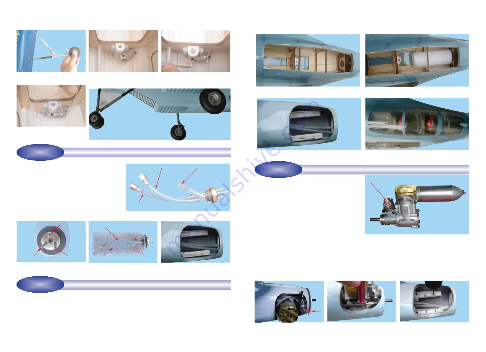
10B - Fuel tank and stopper assembly
(front view)
11B - Fuel tank assembly in position
10C - Illustration of fuel line position-
ing inside cutaway of the tank
11C - Run external pressure, fuel and refuel lines through
the firewall from the tank to the engine area
11D - Re-install the pilots, instrument panel and canopy
10D - Fuel tank installed into the fuse-
lage after adding external fuel lines
from tank forward to engine area
To assemble the fuel tank you will need the following items:
- The fuel tank and fuel stopper assembly (supplied)
- 2 clunks (supplied)
- About 10 in. (25.4 cm) of medium ID silicone fuel line (DUB-
197 or DUB-222 or similar)
10A - Use 2 in. (50 mm) for the pressure line and 4 in. (100
mm) for the fuel and refuel lines.
Pressure line
Connect to the fuel line
Pressure line
Pressure line
Fuel line
Fuel line
Fuel line
Refuel and empty line
Refuel and empty line
Refuel line
STAGE 10
INSTALLING THE FUEL TANK INTO THE FUSELAGE
STAGE 11
11A - Remove the cockpit and instrument panel from the
fuselage
9
INSTALLING THE ENGINE
STAGE 12
The VMAR SU 27 FLANKER is designed for .60 to .91
size two stroke engines. The model has not been designed
to accommodate four stroke or gas powered engines.
12A - .91 2 cycle engine. VMAX 91PRO shown
12B - Allow for gap between the spin-
ner back plate and the fuselage
12C - Mark the location of the engine
mounting holes
12D - Drill 3/32 in. (2 mm) pilot holes
at right angles through the beams
Step 11.1
Remove the external screws and carefully detach the canopy from the fuselage. Then remove the internal screws
and detach the pilots and instrument panel from the fuselage. See 11A
Step 11.2
Install the fuel tank into the fuselage. Use foam sheet (supplied) to cradle the tank. See 11B
Step 11.3
Run external pressure, fuel and refuel lines through the firewall from the tank to the engine area
. Protect the
tubes from contamination See 11C
Step 11.4
After trial fitting the tank and tubing, apply silicone sealant to both sides of the black foam rubber like gasket and
around neck of the tank. Press tank firmly against former . Hold in place until sealant cures.
1/16 in. to 3/32 in. (1.5 to 2.5 mm)
9E - Carefully pull the nose gear oleo
strut out of the fuselage.
9F - Pass the nose gear steering rod
through the EZ connector. Do not
tighten yet.
9G - After re-inserting the nose gear
oleo strut, align and tighten the
steering arm set screw.
9H - Align and secure the EZ connec-
tor to the nose gear steering rod
using the set screw.
9I - Completed installation of the main and nose gear assemblies.
Step 11.5
Re-install the instrument panel and pilots into the fuselage using the internal screws
. Then re-install the
canopy using the external screws See 11D
Step 9.6
Align the nose gear straight ahead and secure the EZ connector to the nose gear steering rod by tightening the
EZ connector set screw. See 9H.


