background image

Depósito legal y copyright. Todos los derechos reservados.


      9

PRO LIFTS S.L.

Quick operation guide

ENGLISH

4.  USER INSTRUCTIONS.

4.1 - 

 Place the lift on a firm, flat surface 

in the area it is to be used with the help of 
the transport wheels (

T

).

4.2 -

 Untighten the security knobs (

K

) and 

remove the legs (

P

) from their transport 

compartment (

S

) and fully insert them into 

their working positions (

V

) checking that 

they are fixed by the pins (

R

).

4.3 -

 Check that the lift is in vertical posi-

tion using the spirit level (

L

) at the base of 

the tower, adjust the stabilizer (

Q

), turning 

the handle (

H

) if necesary.

4.4 -

 Release the forks (

F

) and place them 

in its working position ready to take the 
load on them. Insert the pins to block the 
forks.

4.5 - DO NOT OVERLOAD THE LIFT.

MAXIMUM LOAD IS 270 kg (595 lb) TL-063

The lift should NEVER be overloaded.
Safety at work is the most important is-
sue. Place the load onto the lift using an 
adequate VMB support according to the 
need, use so that the weight of the load 
will only be elevated in a vertical direction. 
The minimum load is 25 Kg.

4.6 -


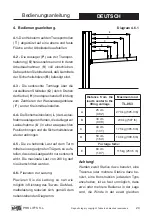
How to place the load:


Always load as close to the tower as 
possible. The maximum load diminishes 
according to the distance from the body 
of the tower as illustrated in the diagram 

4.6.1

, which shows the load on the gravity 

centre with distances to the lifting carriage 
at a maximum lifting. Use a VMB adaptor 
if necessary.

CAUTION

When two towers are used to elevate a 
truss bridge, or many towers to elevate a 
structure of any type, it is almost impossi-
ble that two or more people coordinate the 
winches elevating or lowering the loads, at 
exactly the same pace. At a certain point 
each tower will be extended to different 
height. For this reason it is necessary that 
the structure does not stretch and allows 
for these differences.

With a rigid fixation and if the level diffe

-

rence  is  significant,  the  force  generated 

from the handle of the winch will deform 
the structure and apply a lateral force to 
the lifts causing them to break and block.

WIND SPEED CALCULATIONS

The BGV-C1 is an indoor certification. If you are going to use the 

towerlift outdoor and require a wind speed calculation please con-

tact us, or contact a certified structural engineer.

Summary of Contents for 73938

Page 1: ...OPERATING INSTRUCTIONS USER MANUAL MANUAL DE INSTRUCCIONES TL 063 GB E USA D TOWERLIFT TORRE ELEVADORA TRAVERSENLIFT...

Page 2: ...ropiedad de PRO LIFTS S L Queda prohibida su reproducci n total o parcial por cualquier medio que la tecnolog a actual permita Deposito legal y copyright 2014 Todos los derechos reservados MADE IN SPA...

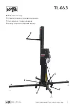
Page 3: ...ht Todos los derechos reservados 3 PRO LIFTS S L F Forks Brazos de carga S Transport compartment Alojamiento de transporte T Transport wheels Ruedas de transporte V Working compartment Alojamiento de...

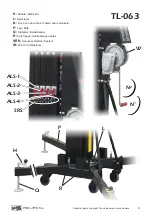
Page 4: ...LIFTS S L H Handle Manivela L Spirit level N Force on hand crank Fuerza sobre manivela P Leg Pata Q Stabilizer Estabilizador R Catch pawl Gatillo bloqueo patas SRS Sequence Retainer System W Winch Ca...

Page 5: ...its all warranty rights to claim VMB reserves the right to modify the pro duct specifications without prior notice The model type production year and se rial number must be quoted in any queries or or...

Page 6: ...esigned to elevate loads upwards in a vertical direction It should NEVER be used as a platform to elevate people 3 3 The maximum load indicated on the characteristics label and the instructions manual...

Page 7: ...st it is carrying a load It is not advisable to carry out any type of horizontal mo vement even small positional adjustments 3 9 NEVER allow any team member below the load or anybody else in the lifts...

Page 8: ...grease or lubricate the winch s braking mechanism The brake disks have been greased with a special heat and pressure resistant solution Other products should not be used to avoid negative effects reg...

Page 9: ...a vertical direction The minimum load is 25 Kg 4 6 How to place the load Always load as close to the tower as possible The maximum load diminishes according to the distance from the body of the tower...

Page 10: ...left in any intermediate position if it is necessary Just stop turning the handle of the winch and gently turn it in an anticlockwise direction N2 to block the last profile risen The ALS lock will ta...

Page 11: ...ct material or fabri cation Damage caused by improper use product modification third party manipula tion or accidental fire are not covered by this warranty If you release your finger from the ALS loc...

Page 12: ...ra el usuario pierde todos los derechos de garant a VMB se reserva el derecho de modificar las especificaciones y las piezas del pro ducto sin previo aviso El tipo de modelo a o de producci n y el n m...

Page 13: ...torre cuando este plegada 3 1 La torre elevadora TL 063 es una m quna dise ada para la elevaci n de cargas en direcci n vertical NUNCA se debe utilizar como plataforma eleavadora de personas 3 3 La ca...

Page 14: ...o de movimiento horizontal ni tan s lo peque os ajustes de posici n 3 9 NUNCA permita que ning n miembro del equipo o cualquier otra persona se sit e debajo de la carga en la zona de operaci n de las...

Page 15: ...er bajados y las patas deben extraerse y colocarse en su posici n de transporte 3 14 No engrasar ni lubricar el mecanismo de freno del cabestrante Los discos de freno vienen engrasados con una soluci...

Page 16: ...los pasadores de seguridad 4 5 LA CARGA M XIMA PARA TL 063 ES 270 kg 595 lb El elevador NUNCA debe ser sobrecarga do La Seguridad en el Trabajo es el ele mento m s importante Coloque la carga en el e...

Page 17: ...horario N1 para elevar el carro y los tramos El sistema de gatillos ALS le per mitir elevar todos los tramos mientras que estos se van bloqueando autom ti camente asegurando que la torre nunca caer Es...

Page 18: ...resistente a la torsi n 4 8 Bloqueo La torre puede dejarse en cualquier po sici n intermedia si se requiere Una vez el sistema esta elevado hasta la altura deseada tan solo deje de girar la mani vela...

Page 19: ...os elementos de elevaci n y sistemas de seguridad que in tervienen en el uso del elevador 5 4 Utilice nicamente piezas de repues to originales para garantizar el nivel de seguridad de forma continuada...

Page 20: ...von Lasten wie Beleuchtungsk rper auf verschiede H hen konzipiert worden 2 3 Zul ssige Hubkraft 270 kg 595 lb 2 4 Mindesthublast 25 Kg 2 5 Zul ssige Hubh he 6 25 m 20 6 2 6 Mindesth he 1 65 m 5 4 2 7...

Page 21: ...gt und nur in vertikaler Richtung hebt 3 2 Achten Sie darauf das der TL 063 Tower auf festem geradenUntergrundsteht UndvergewissernSiesichmitHilfe der Wasserwaage F dass er eine vertikale Position zum...

Page 22: ...den Lift niemals unter Belastung 3 9 Halten Sie sich niemals w hrend des Hebens und Senkens in Gefahrenbereich auf 3 7 Bei Freiluftanwendungen den Turm auf festen Boden stellen und mittels Seilanker g...

Page 23: ...astung ist die berpr fung nicht m glich 3 16 Niemals die Winde oder Teile der Winde unter Be lastung demontieren 3 13 Alle Angebauten Teile sind f r den Transport einzu fahren 3 17 Es sind ausschlie l...

Page 24: ...waagerechten Position bringen und die Sicherheitsbolzen wieder anbringen 4 5 Die zu hebende Last auf dem Turm mittels eines geeigneten Tr gers so aufs tellen dass das Lastgewicht nur senkrecht wirkt...

Page 25: ...dazu lediglich das drehen der Kurbel Die Automatic in der Winde und die Fallbremse sichern die Ladung F r den Transport des Turmes ist dieser durch Senken der Einzelabschnitte herunterzufahren Es ist...

Page 26: ...t vornimmt 5 5 F r die Bestellung von Ersatzteilen ist stets dessen Bestellnummer anzugeben welche den St cklisten Bl ttern dieser Anleitung zu entnehmen ist VMB Service Deutschland Tel 04442 92900 Fa...

Page 27: ...Dep sito legal y copyright Todos los derechos reservados 27 PRO LIFTS S L TL 063 A 1 A 2 6308 6309 5429 C B 6305 6304 6303 6302 6301 D A A 3 A 9 B 4 E 6306...

Page 28: ...l y copyright Todos los derechos reservados 28 PRO LIFTS S L TL 063 A A 3 D 2 6301 6302 6303 6304 6305 6306 A 7 A 7 A 7 A 7 A 8 A 8 A 8 A 8 A 8 A 5 A 5 A 5 A 5 A 5 A 6 A 6 A 6 A 6 A 4 A 9 A 12 A 12 A...

Page 29: ...mm 3 mm 3 mm 1540 3233 3233 2244 2244 1540 3253 3253 3252 3251 3251 7288 7289 Profile 6304 Profile 6303 Profile 6302 A 2 A 1 7208 2152 4005 4004R 7288 7 mm 4 mm 7289 7 mm 4 mm 7289 7 mm 4 mm Profile...

Page 30: ...63 A 8 A 7 5421 7246 7246 8019 A 6 A 4 A 6322 7265 2047 2047 5478 7219 2152 2152 7234 7234 6322 7265 2047 2047 7232 7219 2152 2152 7234 7234 4057 4056 2047x2 7061 2047 2162N 6325 2047 2140 2047 2158 6...

Page 31: ...31 PRO LIFTS S L TL 063 A 13 M14x150 M14x180 A 11 A 11 A 12 A 13 A 6 A 8 7241N 7242 7242 7243 7247 3250 7248 7244B 7245 6306 A 12 7223S 7222N 7061 2044 7061F A A 9 A 10 B 7 6320 6321 2157 3272 2047 6...

Page 32: ...legal y copyright Todos los derechos reservados 32 PRO LIFTS S L TL 063 B 2026 6409 6312 PAT 02 MR PAS 2141 2152 x2 7078 2037 7061 x2 2044 5429 7962 2047 B 1 2140 B 5 B 2 3070D 3070 B 6 B 5 B 6 B 2 B...

Page 33: ...al y copyright Todos los derechos reservados 33 PRO LIFTS S L TL 063 C 7275N 2160 ML 2044 7061 2037 7061 2044 7061 2044 7061 2037 7040 6307 2044 7061 7061 2044 7061 3257 3257 3257 C 1 D Long crank Man...

Page 34: ...Dep sito legal y copyright Todos los derechos reservados 34 PRO LIFTS S L TL 063 2029 2051 2161 2037 2050 2046 6314 2047 2030 2048 2049 Stabilizer kit TL 063 Ref 6313 6309 6308 6311 6310 D 1 D 2 E...

Page 35: ...8x25 2152 M8 Washer Arandela M8 2157 60x15 steel pulley Polea acero 60x15 2158 M12x25 Allen screw Tornillo allen M12x25 2160 ML 900kg Winch Long crank Cabrestante 900kg Manivela larga 2161 Steel hand...

Page 36: ...Perfil acero pata corta TL 063 B Negro 6312 B TL 063 Steel base Base de acero TL 063 B Negro 6313 Complete stabilizer kit TL 063 Estabilizador completo TL 063 6314 TL 063 M18x330mm Threaded bolt Vari...

Page 37: ...ornillo cabeza c nica M8x25 7247 M5x10 Conic screw Tornillo cabeza c nica M5x10 7248 Brake spring Muelle freno de inercia 7265 Pulley support aluminium piece Soporte porta polea cu a aluminio 7275N B...

Page 38: ...Dep sito legal y copyright Todos los derechos reservados 38 PRO LIFTS S L...

Page 39: ......

Page 40: ...8 Paterna Valencia Spain Tlf Export 34 96 171 81 86 Tlf Nacional 96 171 81 83 email info prolifts es web www prolifts es facebook vmblifts Canal VMBLifts Para m s informaci n consulte con nuestros t c...

Reviews: