background image

PENDIENTE

 DE

VALIDACIÓN

 4.2.- LEDs

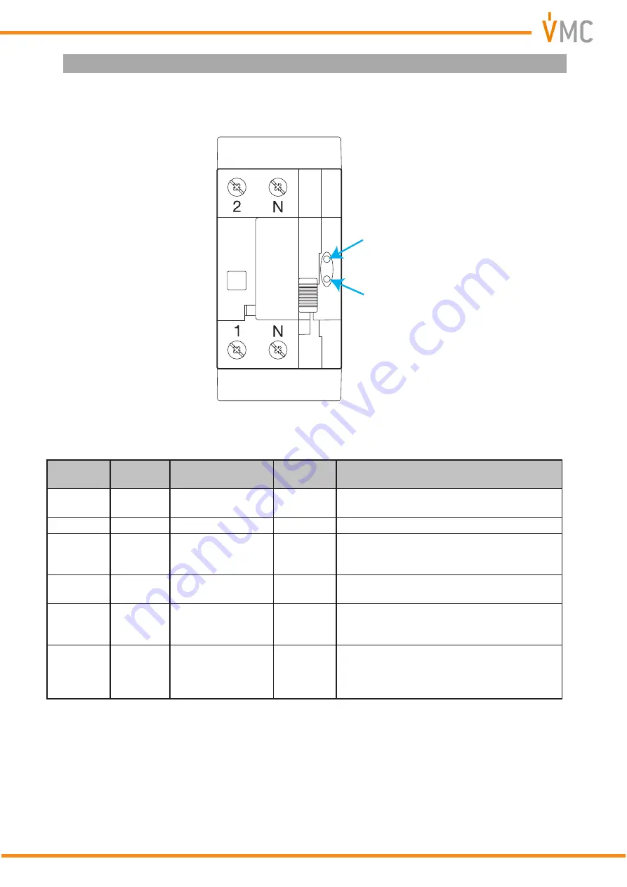
The device has two LEDs: 

AUTO

 in green and 

REC

 in red, which indicate the status of the 


DREC-C

 at all times. (

Figure 6

 and 

Table 4

)

AUTO

REC

AUTO

REC

Figure 6: LEDs DREC-C�

Table 4: LED indications�

AUTO

REC

Operating mode

RCCB 

status

Description

OFF

OFF

Manual

-

Device is manual operating mode. There is no 

power to the 

DREC-C

.

ON

OFF

Automatic

ON

No rearm sequence has been initiated.

ON

Slow 

flashing

Automatic

OFF

Rearm sequence initiated:

Time delay of the rearm sequence (if applica-

ble).

ON

Fast

 flashing

Automatic

OFF

Rearm sequence initiated:

Monitoring the leakage current.

ON 

ON

Automatic

OFF

The maximum number of reclosures has been 

reached. The installation is in permanent fail-

ure mode

Fast 

flashing

Fast 

flashing

Alarm

-

Make  sure  that  the  neutral  connection  has 

been made correctly on the indicated terminal. 

If the device does not reset itself to the correct 

operating mode, contact the TAS.

11

Instruction Manual

DREC-C 

Summary of Contents for DREC Compact

Page 1: ...INSTRUCTION MANUAL M202BVM 03 21A RCCB with automatic reclosing device DREC Compact DREC C...

Page 2: ...2 DREC C Instruction Manual...

Page 3: ...ng should be taken into consideration Incorrect handling or installation of the unit may result in injury to personnel as well as damage to the unit In particular handling with voltages applied may re...

Page 4: ...LATION 7 3 3 CONNECTION 8 3 3 1 CONNECTION DIAGRAM 2 POLE MODEL DREC C 2P 8 3 3 2 CONNECTION DIAGRAM 4 POLE MODEL DREC C 4P 9 4 OPERATION 10 4 1 DESCRIPTION 10 4 2 LEDs 11 4 3 START UP 12 4 3 1 AUTOMA...

Page 5: ...d may differ from the original device SYMBOLS Table 2 Symbols Symbol Description In compliance with the relevant European directive Device covered by European directive 2012 19 EC At the end of its us...

Page 6: ...mode is used for high sensitivity protection so that the device only recloses when the fault that caused tripping has disappeared The rest of the models imple ment the timed reclosing mode to ensure p...

Page 7: ...lting from the use of non original products or accessories or those made by other manufacturers If you detect any operational faults in the device or in its protection system remove the device from se...

Page 8: ...anent failure AUTO and REC LEDs are lit you must check the RCCB and the installation If the installation of the device is done with the RCCB in the OFF state when panel receives voltage the device wil...

Page 9: ...ON DIAGRAM 4 POLE MODEL DREC C 4P CARGA LOAD L3 N L1 L2 Figure 2 Connection diagram DREC C 4P Three phase system CARGA LOAD F N Figure 3 Connection diagram DREC C 4P Single phase system 9 Instruction...

Page 10: ...t important pieces of device LEDs Protection cover TEST key Mode selection switch RCCB Control module Figure 4 Description of the DREC C 2P LEDs Protection cover TEST key Mode selection switch RCCB Co...

Page 11: ...e has been initiated ON Slow flashing Automatic OFF Rearm sequence initiated Time delay of the rearm sequence if applica ble ON Fast flashing Automatic OFF Rearm sequence initiated Monitoring the leak...

Page 12: ...the RCCB cover 5 Put the mode selector switch in Automatic Mode ON Note The switch has an M2 hole where you can attach a seal or a padlock to block access to the RCCB and any other attempts at manual...

Page 13: ...isable the unit s automatic reclosing device Figure 8 The RCCB must be reclosed manually The AUTO and REC LEDs are off Figure 8 DREC C in manual mode with mode selector switch at OFF 4 4 2 AUTOMATIC T...

Page 14: ...s Reclosures 1 2 3 Delay Restart Delay Restart Delay Restart 3 sec 10 sec 20 sec 20 sec 180 sec 60 sec The leakage current will be supervised by measuring the resistance downstream of the tripped RCCB...

Page 15: ...requently Test sequence Figure 10 1 Press the TEST T key 2 Check that the RCCB jumps to OFF position TEST OFF Figure 10 RCCB Test Sequence In the event of a Test sequence failure contact the after sal...

Page 16: ...2P 40 300 300 mA DREC C 2P 63 300 DREC C 4P 40 30 30 mA DREC C 4P 63 30 DREC C 4P 40 300 300 mA DREC C 4P 63 300 Resistance to surges class A AC 250A 8 20 s class S 3000A 8 20 s Resistance to short ci...

Page 17: ...c Colour RAL 7035 Dimensions mm Figure 11 and Figure 12 Standard Residual current operated circuit breakers without integral overcurrent pro tection for household and similar uses RCCB s Part 1 Genera...

Page 18: ...81 91 5 35 5 101 55 87 5 45 76 Figure 12 DREC C 4P dimensions 18 DREC C Instruction Manual...

Page 19: ...al code or that surpasses the limits indicated in the techni cal and environmental features of this manual VMC accepts no liability due to the possible damage to the unit or other parts of the install...

Page 20: ...VMC C Montcada 7 Pol Ind Les Pereres 08130 Santa Perp tua de Mogoda Barcelona Tel 34 935 748 206 Fax 34 935 748 248 www vmc es info vmc es...

Reviews: