9 VBAT-PB VME bus anomaly trigger
VBAT-PB Installation
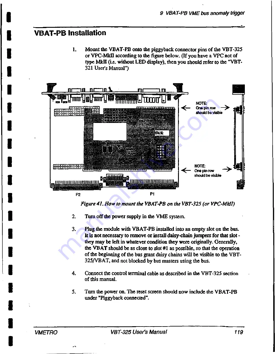
1. M o u n t the VBAT-PB onto the piggyback connector pins of the VBT-325
or VPC-Mkil according to the figure below. (If you have a VPC not of
type Mk (i.e. without LED display), then you should refer to the "VBT-
321 User's Manual")
•
N A N N W A V . W . V . V . V . V . , I N C ,
P2
P
1
NOTE:
4<--- O n e pin row - - >
should be visible
NOTE:
One pin row
>
should be visible
Figure 41. How to mount the VBAT-PB on the VBT-325 (or VPC-Mk11)
2. T u r n off the power supply in the VME system.
3. P l u g the module with VBAT-PB installed into an empty slot on the bus.
It is not necessary to remove or install daisy-chain jumpers for that slot -
they may be left in whatever condition they were originally. Generally,
the VBAT should be as close to slot #1 as possible, so that the operation
of the beginning of the bus grant daisy chains will be visible to the VBT-
325/VBAT, and not blocked by bus masters using the bus.
4. C o n n e c t the control terminal cable as described in the VBT-325 section
of this manual.
5. T u r n the power on. The reset screen should now include the VBAT-PB
under "Piggyback connected".
VMETRO
V
B
T
-
3
2
5
User's Manual
1
1
9
Summary of Contents for VBAT-PB
Page 15: ...x i v 1 1 I 1 1 I I i i I I 1 I I 1 I 1 I I ...
Page 23: ...1VBT 325 Product overview 8 V B T 3 2 5 User s Manual V M E T R O ...
Page 125: ...8 Trace examples 110 V B T 3 2 5 User s Manual V M E T R O ...
Page 144: ...9 VBAT PB VME bus anomaly trigger ITP40 I GND VMETRO V B T 3 2 5 User s Manual 1 2 9 ...
Page 159: ...1 1Jumper settings 144 V B T 3 2 5 User s Manual V M E T R O ...
Page 181: ...16 Simulator for PC 166 V B T 3 2 5 User s Manual V M E T R O ...


