2 Installation
Power supply
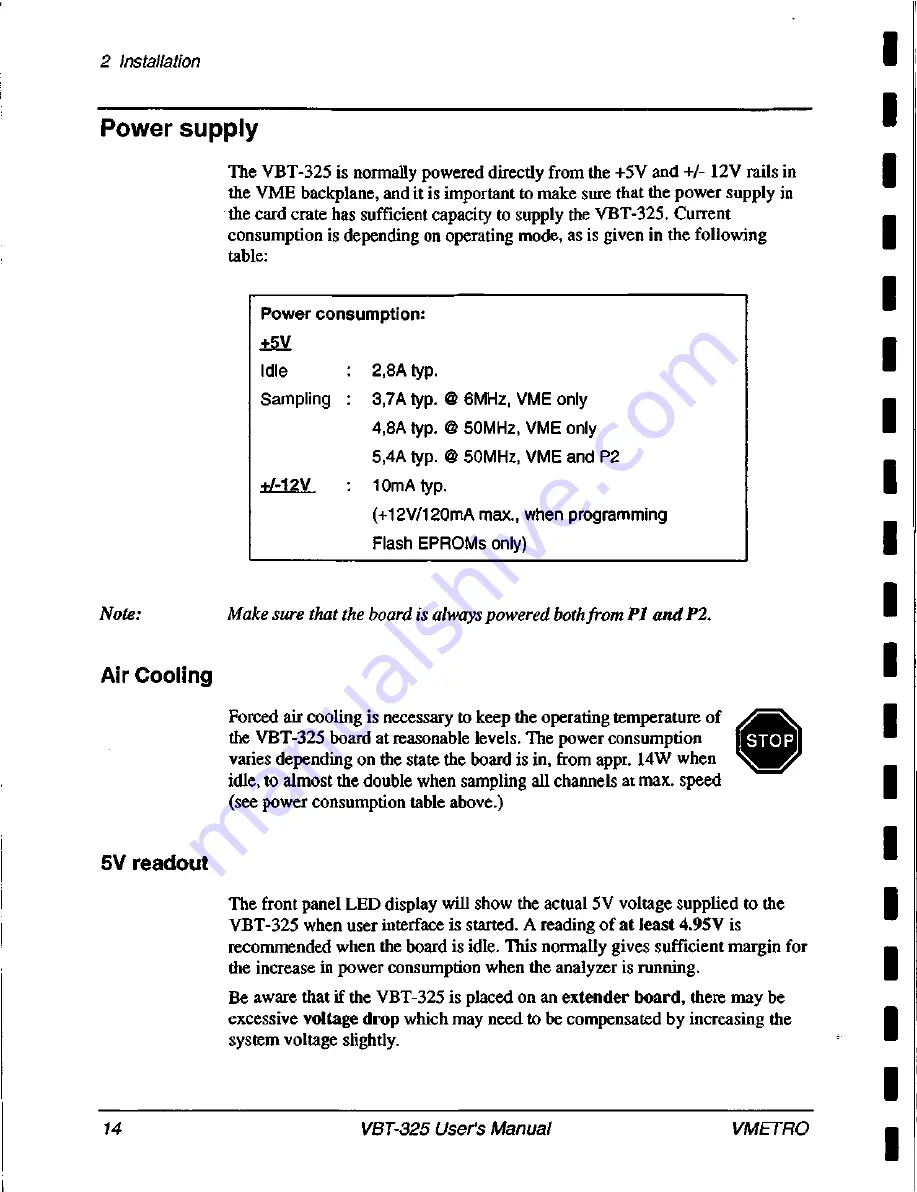
The VBT-325 is normally powered directly from the +5V and +1- 12V rails in
the VME backplane, and it is important to make sure that the power supply in
the card crate has sufficient capacity to supply the VBT-325. Current
consumption is depending on operating mode, as is given in the following
table:
Note:
Air Cooling
5V readout
Power consumption:
+5V
Idle 2 , 8 A typ.
Sampling : 3 , 7 A typ. @ 6MHz, VME only
4,8A typ. @ 50MHz, VME only
5,4A typ. @ 50MHz, VME and P2
+/-12V 1 0 m A typ.
(+12V/120mA max., when programming
Flash EPROMs only)
Make sure that the board is always powered both from
PI and P2.
Forced air cooling is necessary to keep the operating temperature of
the VBT-325 board at reasonable levels. The power consumption
varies depending on the state the board is in, from appr. 14W when
idle, to almost the double when sampling all channels at max. speed
(see power consumption table above.)
The front panel LED display will show the actual 5V voltage supplied to the
VBT-325 when user interface is started. A reading of
at least 4.95V is
recommended when the board is idle. This normally gives sufficient margin for
the increase in power consumption when the analyzer is running.
Be aware that if the VBT-325 is placed on an extender board, there may be
excessive
voltage drop which
may need to be compensated by increasing the
system voltage slightly.
14
V
B
T
-
3
2
5
User's Manual
V
M
E
T
R
O
Summary of Contents for VBAT-PB
Page 15: ...x i v 1 1 I 1 1 I I i i I I 1 I I 1 I 1 I I ...
Page 23: ...1VBT 325 Product overview 8 V B T 3 2 5 User s Manual V M E T R O ...
Page 125: ...8 Trace examples 110 V B T 3 2 5 User s Manual V M E T R O ...
Page 144: ...9 VBAT PB VME bus anomaly trigger ITP40 I GND VMETRO V B T 3 2 5 User s Manual 1 2 9 ...
Page 159: ...1 1Jumper settings 144 V B T 3 2 5 User s Manual V M E T R O ...
Page 181: ...16 Simulator for PC 166 V B T 3 2 5 User s Manual V M E T R O ...


