
13
DOC8003, Rev. B
March, 2003
Elite
Installation Manual
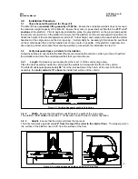
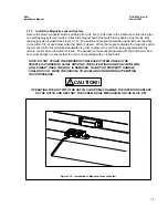
3.12
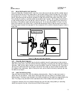
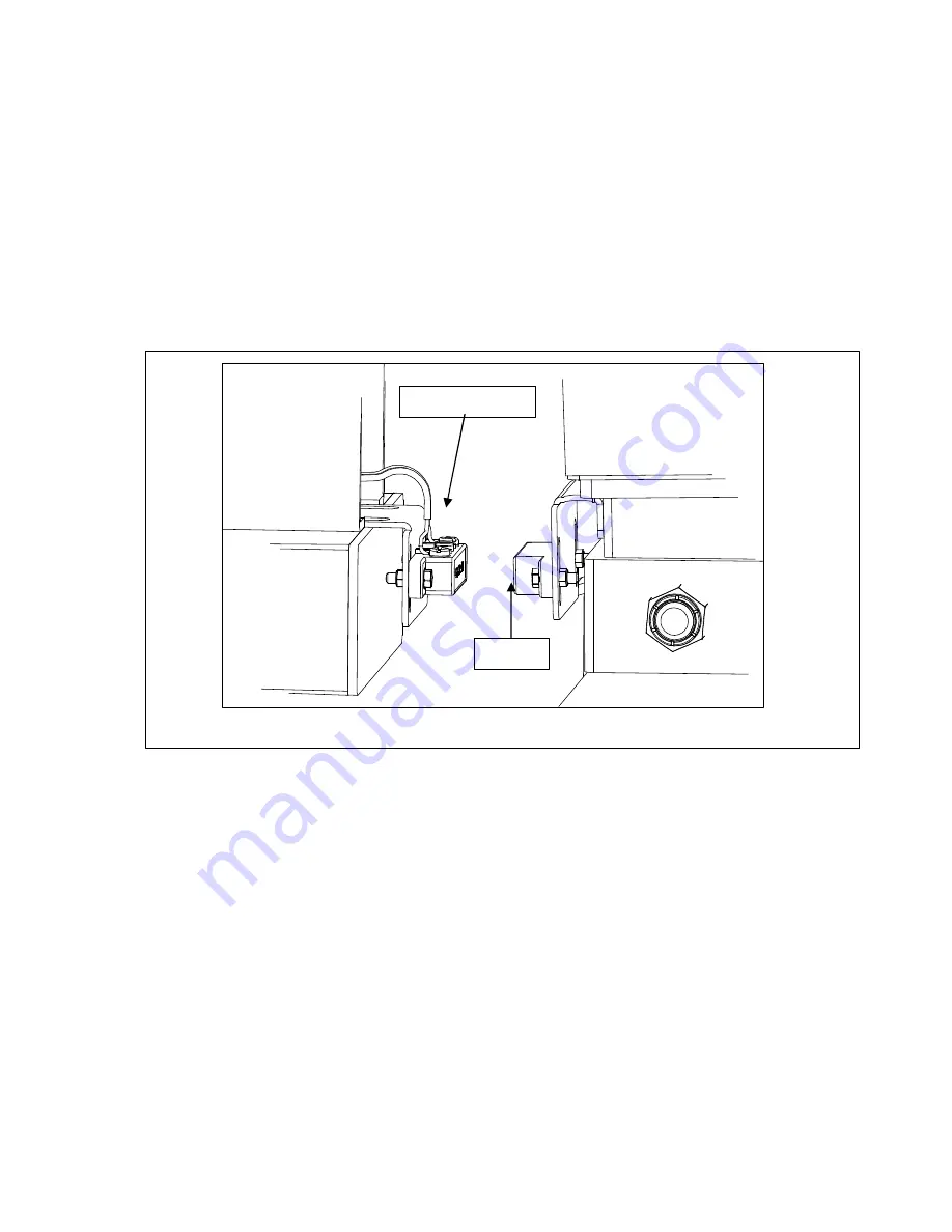
Adjust the Magnetic Limit Switches
Using the transmitter or pendant switch, raise the unit and observe its clearance with the outside bumper.
As the unit reaches the limit of its upward travel, the magnetic switch should shut down the “up” function,
and activate the “in” function. If the unit has not traveled upward sufficiently to clear the threshold of the
vehicle, adjust the magnetic limit switch upwards to trigger the electrical changeover later in the cycle.
This will allow the unit to go up farther before it attempts to travel inwards. Do not adjust the limit switch
so high that the platform never touches the rollers as it travels in. The roller assembly was designed to
bear some of the platform weight during the inward cycle. Do not allow the platform to “hover” over the
track for the duration of its inward travel. The Elite lift was designed with a 3 degree angle to the winch.
This feature was included to compensate for the compression of the vehicle’s suspension system under a
heavy load.
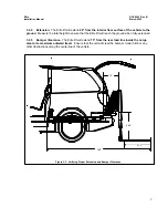
3.13
Check for Door Clearance
Allow the unit to travel in completely ensuring that the platform clears the passenger and driver interior
walls of the cargo space. Once the unit travels inside completely, it will stop when the magnetic switch is
activated. Close the rear hatch carefully to ensure the platform clears the closed rear door. Take care to
observe the scooter/powerchair as it begins to travel into the vehicle to ensure that the headrests clear
the roofline of the cargo space. Before closing the hatch, ensure that the armrests (if present) will clear
the hatch when closed.
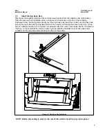
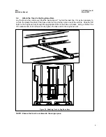
3.14 Install the Retaining Strap
Open the hatch and return the unit to the outside extended position. Place the customer scooter or
powerchair onto the platform. Center the scooter/powerchair onto the platform and install the nylon
retaining strap. The strap can be installed in one of three locations on the platform as appropriate for the
chair. The strap is only intended to limit unwanted motion of the mobility device during transport.
A magnet is included in the kit to hold the retaining strap out of the way during loading or unloading.
Attach the magnet to the face of the Elite winch head for this purpose.
Magnet
Magnetic Switch
Figure 3-9. Magnetic Limit Switch Adjustment


