

3
DOC8003, Rev. B
March, 2003
Elite
Installation Manual
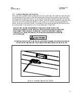
1.
Before Beginning the Installation
Immediately upon receiving the Elite lift, inspect the unit for any damage that may have occurred during
shipping. Notify the carrier immediately of any claims of damage.
Included in the documentation package is a yellow warranty card which is to be filled out completely by
the installing organization and returned to VMI within 10 days of the installation of the lift.
NOTE: THE WARRANTY CARD MUST BE PROCESSED IN
ORDER TO ACTIVATE THE WARRANTY.
The lift serial number can be found on the silver sticker on the winch of the Elite lift. Record this number
and all other requested information on the card, detach it from the larger portion of the warranty record
and mail to VMI postage paid.
2.
Return Authorization Procedure
a. In the event of a failure or product replacement, contact VMI Technical Support at 1-800-348-8267
for a return authorization. You may fax a claim to 602-304-3277.
b.
Once approved, VMI Technical Support will mail a return authorization tag to the dealership.
c.
All components should be carefully packaged in the original package if possible for shipment.
d.
The carrier will pick up the unit and return it to VMI for assessment.
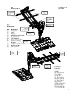
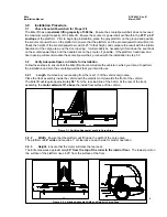
3.
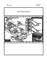
Packing List and Required Tools for Installation
Refer to the illustrations on Page 4 for a breakdown of the components that comprise the Elite lift. Also
included is a list of the tools required to properly install the Elite lift.
Prior to Installation


