500-003124-000
3-6
3.8
CHANNEL SEQUENCER AND DUAL-PORTED RAM MEMORY
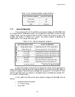
The VMIVME-3124 is normally operated in the scanning mode. When the
board is powered up or reset, conversions start immediately. Once the A/D conversion
is completed, the Dual-Port control logic takes the converted data and stores it in the
channel's appropriate Dual-Port register. The channel counter is incremented by one,
which selects the next channel to be multiplexed to the ADC. After selecting the next
channel, a new A/D conversion sequence is initiated. When all input channels have
been converted and stored (16 or 32), the channel counter is reset and the channel
scanning sequence is started again.
The Stop Auto Scan bit in the Control/Status Register may be set to halt the
channel sequencer at its current address. This address may be read from the Channel
Pointer Register. This feature allows the controlling software to lock onto a channel
and digitize it at the maximum rate of 40 kHz. Please note that the desired channel
can not be directly set. The software must wait for the desired channel to appear in the
Channel Pointer register. It then sets the Stop Auto Scan bit within 25
sec.
3.9
BOARD ID REGISTER
The first location in the VMIVME-3124 register set is a read-only Board ID
Register. It always reads $30. Other VMIC products have similar registers which read
different constants. This allows general-purpose system software to automatically
determine any installed boards.
3.10
BUILT-IN POWER CONVERTER AND ADC POWER SUPPLY
Electrical power for the VMIVME-3124 analog circuitry is supplied by an
on-board DC-to-DC converter. The converter tran5 VDC power from the
VMEbus into a regulated
15 VDC power. The VMIVME-3124 does not require any
12 VDC from the VMEbus.
The ADC's +5 VDC logic power is provided by an on-board voltage
regulator. Some of the +15 VDC from the DC-to-DC converter’s output is used as the
input voltage to this regulator.


