background image

9

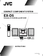
The Digital-1 uses two types of connections: balanced XLR and unbalanced ¼” . One of these 

connections must be made to the mixer or sound system in order for sound to be heard .

USING THE UNBALANCED ¼”:

• Connect one end of the ¼” cable into the Mixed Output jack located on the back of the Digital-1 

receiver .

• Connect the other end of the ¼” cable into a unbalanced microphone input jack on the mixer or 

sound system being used .

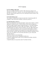
USING THE BALANCED XLR:

• Connect the female end of a balanced XLR cable into the Balanced Output jack located on the back 

of the Digital-1 receiver .

• Connect the male end of the balanced XLR cable into a balanced microphone input jack on the mixer 

or sound system being used .

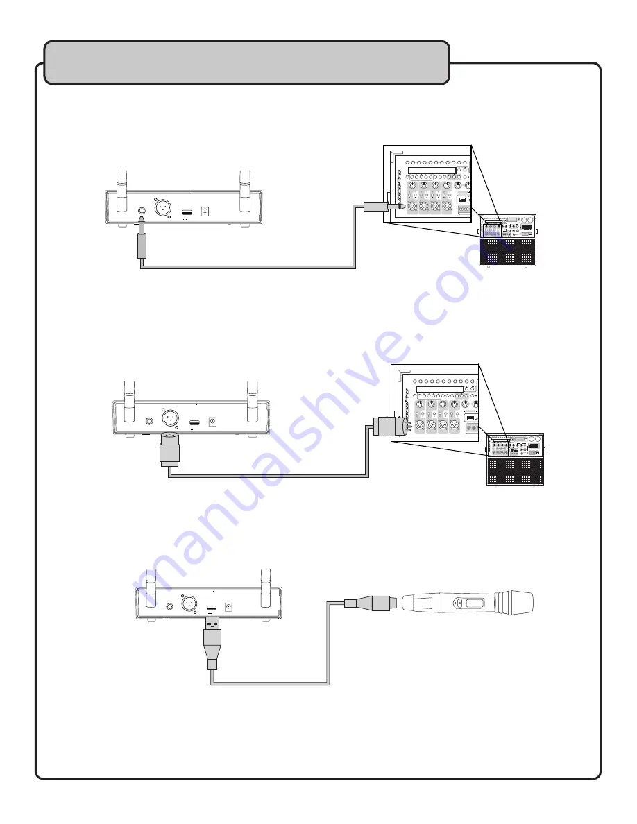
USING THE USB RECHARGE JACK:

• Connect one of a micro-USB cable into the USB Charge Output located on the back of the Digital-1 

receiver .

• Connect the other end of the micro-USB cable into the USB Charge jack located on the bottom end 

of the microphone .

GETTING CONNECTED

D S P  

REVERB 

LAPTOP 

VIDEO 

DELAY 

TREBLE 

USB 

SD CARD RECORDER

BASS 

CH 1  CH 2  CH 3  CH 4 

MIN 

MAX 

GAIN 

MIN 

MAX 

GAIN 

MIN 

MAX 

GAIN 

MIN 

MAX 

GAIN 

PBC 

+10 

VOCAL C/P 

DIGITAL KEY CONTROL 

EJECT  PLAY/PAUSE 

MIC 

EFFECT ON 

LINE 

EFFECT OFF 

MIC 

EFFECT ON 

LINE 

EFFECT OFF 

MIC 

EFFECT ON 

LINE 

EFFECT OFF 

MIC 

EFFECT ON 

LINE 

EFFECT OFF 

REPEAT 

HISS FILTER 

REVERB VOLUME  

MIN 

60Hz 

+12dB 

-12dB 

0dB 

+12dB 

-12dB 

0dB 

1KHz  3KHz  6KHz  16KHz 

200Hz  400Hz 

60Hz 

1KHz  3KHz  6KHz  16KHz 

200Hz  400Hz 

MAX 

MIN 

MAX 

HEADPHONES 

Mp3 

AV1 INPUT 

INPUT SELECT 

POWER 

DSP EFFECTS 

MUSIC EQ 

MIC/LINE MASTER 

MUSIC MASTER 

MIC/LINE TONE 

ON 

AV1 

AV2 

USB 

SD CARD 

Mp3 

LAPTOP 

DVD 

OFF 

VOLUME 

HERO-REC

120W 4 Channel Multi-Format Portable  

PA System With Digital Reverb 

STEREO ECHO DSP 

SD

RECORD

PREV

NEXT

B-SCAN F-SCAN

AM/FM

MUTE

L/R

FOLDER

REPEAT

PRESET

SEARCH

ST/MONO AUTO

TUNER 

STOP/DEL

   REC INDIC

ATOR


FAST BLINK: 

W AIT

   SLOW BLINK: READY

   SOLID: RECORDING

VIDEO 

TREBLE 

USB 

SD C

BASS 

CH 1  CH 2  CH 3  CH 4 

MIN 

MAX 

GAIN 

MIN 

MAX 

GAIN 

MIN 

MAX 

GAIN 

MIN 

MAX 

GAIN 

PBC 

+10 

VOCAL C/P 

DIGITAL KEY CONTROL 

EJECT  PLAY/PAUSE 

MIC 

EFFECT ON 

LINE 

EFFECT OFF 

MIC 

EFFECT ON 

LINE 

EFFECT OFF 

MIC 

EFFECT ON 

LINE 

EFFECT OFF 

MIC 

EFFECT ON 

LINE 

EFFECT OFF 

AV1 INPUT 

MIC/LINE TONE 

SD

RECORD

PREV

NEXT

B-SCAN F-SCAN

AM/FM

MUTE

L/R

FOLDER

REPEAT

PRESET

SEARCH

ST/MONO AUTO

STOP/DEL

USB CHARGE OUTPUT

5V        500 mA

USB CHARGE OUTPUT

5V        500 mA

D S P  

REVERB 

LAPTOP 

VIDEO 

DELAY 

TREBLE 

USB 

SD CARD RECORDER

BASS 

CH 1  CH 2  CH 3  CH 4 

MIN 

MAX 

GAIN 

MIN 

MAX 

GAIN 

MIN 

MAX 

GAIN 

MIN 

MAX 

GAIN 

PBC 

+10 

VOCAL C/P 

DIGITAL KEY CONTROL 

EJECT  PLAY/PAUSE 

MIC 

EFFECT ON 

LINE 

EFFECT OFF 

MIC 

EFFECT ON 

LINE 

EFFECT OFF 

MIC 

EFFECT ON 

LINE 

EFFECT OFF 

MIC 

EFFECT ON 

LINE 

EFFECT OFF 

REPEAT 

HISS FILTER 

REVERB VOLUME  

MIN 

60Hz 

+12dB 

-12dB 

0dB 

+12dB 

-12dB 

0dB 

1KHz  3KHz  6KHz  16KHz 

200Hz  400Hz 

60Hz 

1KHz  3KHz  6KHz  16KHz 

200Hz  400Hz 

MAX 

MIN 

MAX 

HEADPHONES 

Mp3 

AV1 INPUT 

INPUT SELECT 

POWER 

DSP EFFECTS 

MUSIC EQ 

MIC/LINE MASTER 

MUSIC MASTER 

MIC/LINE TONE 

ON 

AV1 

AV2 

USB 

SD CARD 

Mp3 

LAPTOP 

DVD 

OFF 

VOLUME 

HERO-REC

120W 4 Channel Multi-Format Portable  

PA System With Digital Reverb 

STEREO ECHO DSP 

SD

RECORD

PREV

NEXT

B-SCAN F-SCAN

AM/FM

MUTE

L/R

FOLDER

REPEAT

PRESET

SEARCH

ST/MONO AUTO

TUNER 

STOP/DEL

   REC INDIC

ATOR


FAST BLINK: 

W AIT

   SLOW BLINK: READY

   SOLID: RECORDING

VIDEO 

TREBLE 

USB 

SD C

BASS 

CH 1  CH 2  CH 3  CH 4 

MIN 

MAX 

GAIN 

MIN 

MAX 

GAIN 

MIN 

MAX 

GAIN 

MIN 

MAX 

GAIN 

PBC 

+10 

VOCAL C/P 

DIGITAL KEY CONTROL 

EJECT  PLAY/PAUSE 

MIC 

EFFECT ON 

LINE 

EFFECT OFF 

MIC 

EFFECT ON 

LINE 

EFFECT OFF 

MIC 

EFFECT ON 

LINE 

EFFECT OFF 

MIC 

EFFECT ON 

LINE 

EFFECT OFF 

AV1 INPUT 

MIC/LINE TONE 

SD

RECORD

PREV

NEXT

B-SCAN F-SCAN

AM/FM

MUTE

L/R

FOLDER

REPEAT

PRESET

SEARCH

ST/MONO AUTO

STOP/DEL

IR

USB CH AR GE OUTPU T

5V        500  mA

Summary of Contents for Digital-1

Page 1: ...Digital 1 Digital Wireless Microphone with Mic On Chip Technology o w n e r s m a n u a l IR ...

Page 2: ......

Page 3: ...3 TABLE OF CONTENTS Safety 4 FCC Information 5 Welcome 6 Listening 7 Specifications 8 Getting Connected 9 Descriptions and Functions 10 Operations 13 Commonly Asked Questions 16 ...

Page 4: ...ances including amplifiers that produce heat 10 Power Sources The appliance should be connected to a power supply only of the type described in the operating instructions or as marked on the appliance 11 Grounding or Polarization Precautions should be taken so that the grounding or polarization means of an appliance is not defeated 12 Power Cord Protection Power supply cords should be routed so th...

Page 5: ...ace for future reference 2 Install your unit in a cool dry clean place away from windows heat sources and too much vibration dust moisture or cold Avoid sources of hum transformers electric motors To prevent fire or electrical shock do not expose to rain and water 3 Do not operate the unit upside down 4 Never open the cabinet If a foreign object drops into the set contact your dealer 5 Place the u...

Page 6: ...rtiss Court La Verne CA 91750 Toll Free 800 678 5348 TEL 909 593 8893 FAX 909 593 8890 VocoPro Company Email Directory Customer Service General Information info vocopro com Tech Support techsupport vocopro com Remember Our Website Be sure to visit the VocoPro website www vocopro com for the latest information on new products packages and promos And while you re there don t forget to check out our ...

Page 7: ...t there Pay attention to the different levels in various recordings Taking a minute to do this now will help to prevent hearing damage or loss in the future After all we want you listening for a lifetime Used wisely your new sound equipment will provide a lifetime of fun and enjoyment Since hearing damage from loud noise is often undetectable until it is too late this manufacturer and the Electron...

Page 8: ...30 20 KHz 2dB Signal Noise Ratio 96dB Receiving Sensitivity 95dBm Transmission Delay 3 ms Power Supply DC12V 1A Audio Output 1x 1 4 1 x XLR balance output MICROPHONE Frequency Switch IR SYNC Output Power 0 40 mW Harmonic Radiation 50 dBc Battery 1x18500 Lithium Battery Life 8h WHAT S IN THE BOX Power Adapter 1 8 1 8 stereo cable Lithium Battery 18500 USB Charge Cable Digital 1 Reciever Digital 1 M...

Page 9: ...PEAT PRESET SEARCH ST MONO AUTO TUNER STOP DEL REC INDIC ATOR FAST BLINK W AIT SLOW BLINK READY SOLID RECORDING L VIDEO TREBLE USB SD C BASS CH 1 CH 2 CH 3 CH 4 MIN MAX GAIN MIN MAX GAIN MIN MAX GAIN MIN MAX GAIN PBC 1 2 3 4 5 6 7 8 9 0 10 VOCAL C P DIGITAL KEY CONTROL EJECT PLAY PAUSE MIC EFFECT ON LINE EFFECT OFF MIC EFFECT ON LINE EFFECT OFF MIC EFFECT ON LINE EFFECT OFF MIC EFFECT ON LINE EFFE...

Page 10: ...tery level graphic frequency analyzer and menus a Display Icons RF Indicates signal intensity The stronger the signal the more the bar is filled AF Indicates the audio level The louder the audio the more the bar is filled Indicates microphone battery level The indicator will display remaining battery power Indicates the receiver is sending new settings through the IR sensor to the microphone 7 Unl...

Page 11: ... audio out to a mixer or sound system 3 XLR Output This balanced XLR output sends the microphone audio out to a mixer or sound system 4 USB Charge Output This USB will charge the microphone Output current 500mA 5V 5 Power In This is where the receivers power adapter is connected DESCRIPTIONS AND FUNCTIONS 1 2 5 4 3 1 USB CHARGE OUTP U T 5V 500 m A ...

Page 12: ...uted Press power button once to toggle the mute feature Hi Lo This is the microphone transmission status Frequency This is the current Group Channel with the corresponding frequency 2 IR Sensor This is used to pair and sync the microphone with the receiver 3 Power This toggles the microphone power Press and hold to power off on 4 USB Charge Port This is where the USB charge cable connects DESCRIPT...

Page 13: ...can option with the Selector Knob 3 Select which half of the spectrum will be scanned either Up or Down 4 Use Selector Knob to confirm selection and start Frequency Scan 5 Once Scan is complete hold microphone IR sensor in line and within 4 inches of the IR sensor located near the display 6 Press the IR button to communicate the new frequency to the microphone OPERATIONS 1 5 4 6 AF GR CH SCAN TX P...

Page 14: ...ups There are 6 channels within each Group 4 Use the Selector Knob to confirm selections 5 Once confirmed hold the microphone IR sensor in line and within 4 inches of the IR sensor located near the display 6 Press the IR button to communicate the new frequency to the microphone NOTE Each channel is one microphone frequency OPERATIONS AF GR CH SCAN TX PWR 919 10 MHz 01 06 RF HI GR CH 1 5 4 6 AF GR ...

Page 15: ...ighlight and select the TX PWR option with the Selector Knob 3 Select from either High or Low to modify the output power 4 Once output power has been modified hold the microphone IR sensor in line and within 4 inches of the IR sensor located near the display 5 Press the IR button to communicate the new power level to the microphone 1 5 4 6 AF GR CH SCAN TX PWR 919 10 MHz 01 06 RF HI GR C H AF GR C...

Page 16: ...rs are not aligned or within range when pairing Be sure the microphone and receiver sensors are aligned and within 4 inches of eachother Power the micrphone off on to reset the microphone 3 WHAT DOES UP DOWN MEAN IN THE FREQUENCY ANALYZER The UP DOWN scan feature refers to the Frequency Analyzer searching above or below the currently set frequency Select up to find a higher frequency Select down t...

Page 17: ...rovide reasonable protection against harmful interference in a residential installation This equipment generates uses and can radiate radio frequency energy and if not installed and used in accordance with the instructions may cause harmful interference to radio communications However there is no guarantee that interference will not occur in a particular installation If this equipment does cause h...

Reviews: