11
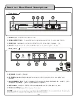
1. POWER button
- Turns the UHF-3205 On and Off.
2. SIGNAL INDICATOR LEDs
- These will light up when signals are received from the microphone channels.
3. POWER (LED)
- Indicates whether the UHF-3205 is ON or OFF. When it is lit, the power is ON.
4. VOLUME controls
- Adjusts the individual VOLUME of the receiver’s 2 microphone channels.
5. ANTENNAS
- Provide the RF signal.
6. AC POWER connection
- Main power jack for connection to an AC electrical outlet or power strip/surge
protector.
7. MIC CHANNEL OUTPUTS
- These ¼” outputs are for connection to amplifiers, effects devices or mixers. OUT A
corresponds to CHANNEL 1 and OUT B corresponds to CHANNEL 2.
8. MIXED OUTPUT
- Output mic channels A and B simultaneously from this output using a ¼” cable.
9. POWER ADAPTER (charger)
- Provides power the receiver.
CAUTION:
Make sure you connect the power adapter labeled “RECEIVER” to the receiver’s AC input. Connecting the
wrong adapter to the receiver could damage the unit and void the warranty.
Front and Rear Panel Descriptions
Front panel
Rear panel
2
2
3
1
4
Microphone Descriptions
�
Summary of Contents for UHF-3205
Page 16: ...C T M R ...


