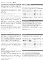
ACHTUNG!
Bei der Montage von Heizkörpern ist zu beachten, dass die Befestigung von
Heizkörpern so dimensioniert wird, dass sie für die bestimmungsgemäße Verwendung und
vorhersehbarer Fehlanwendung geeignet ist. Hierbei sind insbesondere die Verbindung
mit dem Baukörper sowie dessen Beschaffenheit, die Geeignetheit des Montagezubehöres
und die möglichen Belastungen nach erfolgter Montage zu prüfen.
Die Installation und Inbetriebnahme Ihres Badheizkörpers ist von einer zugelassenen Fach-
fi rma durchzuführen. Bei der Installation sind die einschlägigen Normen bzw. die natio-
nalen elektrotechnischen Sicherheitsvorschriften, wie ÖVE- und VDE-Bestimmungen zu
beachten.
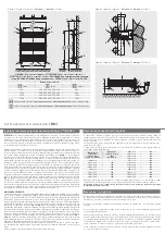
Unter Berücksichtigung der geometrischen Maße des Heizkörpers und der Anschlussele-
mente (Ventile, Verschraubungen) - siehe
(Abb. 1)
- ist die Verrohrung vorzubereiten. Wir
empfehlen, einen seitlichen Mindestabstand zum Heizkörper von 100 mm einzuhalten. Da-
bei ist Nachfolgendes zu berücksichtigen:
Wird eine Elektroheizpatrone nicht verwendet, werden für den Vorlauf- und Rücklaufan-
schluss die 1/2“ Muffen
II
bzw
I
genutzt. Aus optischen Gründen wird für diese Produkte oft
der reitende Anschluss, d. h. Vorlauf unten, Rücklauf unten empfohlen.
Bei Verwendung einer Elektroheizpatrone kann diese direkt in eine der Muffen
I
eingedich-
tet werden, wenn eine der Muffen
II
für den Vorlauf genutzt wurde.
Für den Fall eines reitenden Hydraulikanschlusses, d. h. Vorlauf unten, Rücklauf unten muss
in eine der beiden 1/2“ Muffen
I
das verchromte T-Stück
T
eingedichtet
werden, in das neben dem hydraulischen Anschluss auch die Elektroheizpatrone einge-
dichtet werden kann
(Abb. 3)
. Dabei sind die Hinweise der Montageanleitung für das PTC-
Elektroheizelement zu beachten. Die Verwendung des Elektroheizelements muss im Zuge
der Erstmontage des Badheizkörpers berücksichtigt werden. Eine spätere Elektroheizpatro-
nenmontage ist nur mehr mit großem Montageaufwand möglich.
Die nicht verwendeten Anschlüsse mit den beigepackten Stopfen verschließen, wobei in
eine der beiden Muffen
II
die 1/2“ Entlüftung zu montieren ist.
WANDMONTAGE:
Anreißen, Bohren der Löcher
A
- Bohrer Ø10 - und Setzen der Dübel entsprechend den
Aufhängungsmaßen -
(Abb. 1)
.
Befestigung der oberen Wandfüße
5
und waagrechtes Ausrichten derselben, wobei die
versenkten Langlochbohrungen
4
in den Wandfüßen nach unten stehen müssen. Dabei
sollen die Wandmontageschrauben
6
mit Beilagescheiben in der Mitte der Langlöcher der
Wandfüße montiert werden. Festziehen des unteren Montagestutzens
2
und Klemmteil
1
zwischen den horizontalen Rohren des Heizkörpers mit der Kreuzschlitzschraube
3 (Abb.
1 u. 2)
.
Aufstecken des unteren Wandfußes
B
auf den Montagestutzen
2
und mit Linsenkopfschrau-
be 7 befestigen (dient als Distanzierung - vertikales Ausrichten).
Wandmontage des Heizkörpers: Die oberen Montagestutzen
2
werden in die Wandfüße
5
gesteckt und mittels Linsenkopfschraube
7
miteinander verbunden, Heizkörper mit Klemm-
teil
1
und Kreuzschlitzschraube
3
befestigen, Abdeckkappen
8
aufstecken
(Abb. 1 u. 2)
.
Durch das versenkte Langloch im Wandfuß kann der Wandabstand variiert werden. Dies gilt
auch für den unteren Wandfuß zur vertikalen Ausrichtung des Heizkörpers.
Verstellmöglichkeiten der Wandfüße in Bauhöhenrichtung ist durch das Langloch
9
im
Wandfuß gegeben, sollten die hydraulischen Anschlüsse nicht genau passen.
Heizkörper hydraulisch anschließen.
Installation/Montage Badheizkörper Cosmo STANDARD
Die eleganten Badheizkörper sind geeignet für Warmwasserzentralheizungen mit max. Be-
triebstemperatur von 110 °C und max. Betriebsüberdruck von 10 bar.
Der gleichbleibende hohe Qualitätsstandard unterliegt einer laufenden Eigen- und Fremd-
überwachung.
Nacharbeiten am Heizkörper (z.B. Schweißarbeiten) durch den Kunden sind nicht erlaubt.
Die Badheizkörper können auch mit einer Elektrozusatzheizung ausgestattet werden, wobei
die nachfolgenden Empfehlungen einzuhalten sind:
Heizkörperbeschreibung
Heizkörperdimension
Baulänge x Bauhöhe
[mm]
PTC-heizelement
[W] bei 60 °C
400 x 714
400 x 1134
400 x 1470
400 x 1764
500 x 714
500 x 1134
500 x 1470
500 x 1764
-
300
300
300
300
300
300
600
M o n t a g e a n l e i t u n g
( D )
A s s e m b l y m a n u a l
( G B )
Bedienung und Pflege
Die Badheizkörper sind hochwertige Produkte, die nicht nur der Raumheizung dienen, son-
dern die auch zur Trocknung von Handtüchern geeignet sind. Daher ist zu beachten, dass
sie heiße Oberfl ächen besitzen. Es dürfen nur Textilien, die mit Wasser gewaschen wurden,
getrocknet werden.
Selbstverständlich ist es unzulässig, diesen Heizkörper als Kletter- oder Sportgerät zu be-
nutzen.
Zur Reinigung der Heizkörperoberfl ächen sind schonende, nicht scheuernde Reinigungs-
mittel zu verwenden.
Für den Fall des Elektroheizungsbetriebes muss die Heizwasserausdehnung immer bis zum
Expansionsgefäß gewährleistet sein, z. B. durch Öffnen des Rücklaufventiles. Um Wärme-
verschleppungen in das Heizungsnetz zu vermeiden, wird in diesem Fall empfohlen, das
Thermostatventil zu schließen. Selbstverständlich darf die Elektroheizung nur in Betrieb ge-
nommen werden, wenn der Heizkörper komplett mit Heizungswasser gefüllt ist.
Wird der Heizkörper elektrisch betrieben, darf er aus sicherheitstechnischen Gründen nicht
komplett abgedeckt werden.
Die hydraulische Leistungsregelung - Raumtemperaturregelung - erfolgt bei den Badheiz-
körpern durch ein extern montiertes Heizkörperthermostatventil.
Das Wandmontagekonzept ist ein auf fertige Wände konzipiertes System.
600 x 714
600 x 1134
600 x 1470
600 x 1764
750 x 714
750 x 1134
750 x 1470
750 x 1764
900 x 714
900 x 1134
900 x 1470
900 x 1764
300
300
600
600
300
600
600
600
300
600
600
900
ATTENTION!
For the correct installation of radiators it is essential that the fi xing of the radi-
ator is carried out in such a way that it is suitable for intended use AND predictable misuse.
A number of elements need to be taken into consideration including the fi xing method
used to secure the radiator to the wall, the type and condition of the wall itself, and any
additional potential forces or weights, prior to fi nalising installation.
The installation and startup of your bathroom heating element must be performed by an
authorized installation company. The applicable standards and national electrotechnical
safety regulations such as the ÖVE and VDE regulations must be observed for installation.
The piping must be prepared in consideration of the geometric dimensions of the heating
element and the connection elements (valves, screw connections) – see
(Fig. 1)
. We recom-
mend maintaining a space of at least 100 mm on the sides of the heating element. Please
also note the following:
If an electrical heating cartridge is not used, the 1/2“ tapping
II
and
I
are used for the sup-
ply and return connection. To improve the appearance of the installed unit, connection is
often recommended with the fl ow and return connected at the bottom 2 tapping‘s
I
+
I
.
When using an electrical heating cartridge, this can be sealed directly into one of the tap-
ping
I
, if one of the tapping
II
is used for the supply connection. In the case of a straddling
hydraulic connection, that is, supply below, return below, the chromed T-piece
T
must be
sealed into one of the two 1/2“ tapping. The electrical heating cartridge can then also be
sealed into the T-piece
T
in addition to the hydraulic connection
(Fig. 3)
. The installation
instructions for the PTC electroheating element must be observed. The use of the electrical
heating element must be considered when installing the bath heating element for the fi rst
time. Subsequent installation of the electrical heating cartridge is only possible with great
diffi culty.
Close the unused connections with the plugs supplied, whereby the 1/2“ air bleed must be
installed in one of the two tapping
II
.
WALL INSTALLATION:
Marking, drilling of the holes
A
– drill diameter 10 – and placement of the pins according
to the mounting dimensions
(Fig. 1)
.
Fastening of the top wall feet
5
and horizontal alignment of these feet, whereby the sunken
oblong holes
4
in the wall feet must face downward. The wall mounting screws
6
must be
mounted in the center of the oblong holes of the wall feet with shims. Tighten the lower
mounting connector
2
and clamping piece
1
between the horizontal pipes of the heating
element with the Phillips screw
3 (Fig. 1 and 2)
.
Attach the lower wall foot
B
to the mounting connector
2
and fasten it with the tallow-drop
screw
7
(serves as spacer – vertical alignment).
Wall mounting of the heating element: Insert the top mounting connectors
2
into the wall
feet
5
and connect them together with tallow-drop screws
7
, fasten the heating element
with clamping piece
1
and Phillips screw
3
, attach the end caps
8 (Fig. 1 and 2)
. The distan-
ce to the wall can be varied with the sunken oblong hole in the wall foot. This also applies
to the lower wall foot for vertical alignment of the heating element.
Oblong hole
9
in the wall foot offers vertical adjustment options for the wall feet in case the
hydraulic connections do not fi t exactly.
Hydraulically connect the heating element.
Installation/Montage of bathroom heating element Cosmo STANDARD
The elegant bathroom heating elements are suitable for central warm water heating with a
max. operating temperature of 110 °C and max. operating overpressure of 10 bar. The con-
sistently high quality standard is subject to continuous internal and third-party monitoring.
Alterations to the heating element (e.g. welding work) by the customer are not
permitted.
The bathroom heating elements can also be equipped with supplemental electrical heating,
whereby the following recommendations should be observed:
Heating element description
Heating Element
Dimensions [mm]
Width x Height
PTC-
Electrical heating
[W] at 60 °C
400 x 714
400 x 1134
400 x 1470
400 x 1764
500 x 714
500 x 1134
500 x 1470
500 x 1764
-
300
300
300
300
300
300
600
Operation and care
The bathroom heating elements are high-quality products that serve not only to heat the
room, but are also suitable for drying of hand towels. It is therefore important to note that
they have hot surfaces. Only textiles that have been washed in water may be dried.
Naturally, it is not permitted to use the heating elements as climbing objects or for games.
Use gentle, non-abrasive cleaning agents to clean the heating element surfaces.
When using the supplemental electrical heating, hot water expansion into the expansion
tank must always be guaranteed, e.g. by opening the return valve. To prevent transmission
of heat to the heating network, closing of the thermostat valve is recommended in this case.
Naturally, the electrical heating may only be started when the heating element is completely
fi lled with heating water.
If the heating element is operated electrically, it must not be completely covered for safety
reasons.
The hydraulic output regulation – room temperature regulation – for the bathroom heating
elements is performed with an externally installed heating element thermostat valve.
The wall mounting concept is a system designed for fi nished walls.
600 x 714
600 x 1134
600 x 1470
600 x 1764
750 x 714
750 x 1134
750 x 1470
750 x 1764
900 x 714
900 x 1134
900 x 1470
900 x 1764
300
300
600
600
300
600
600
600
300
600
600
900


