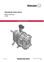
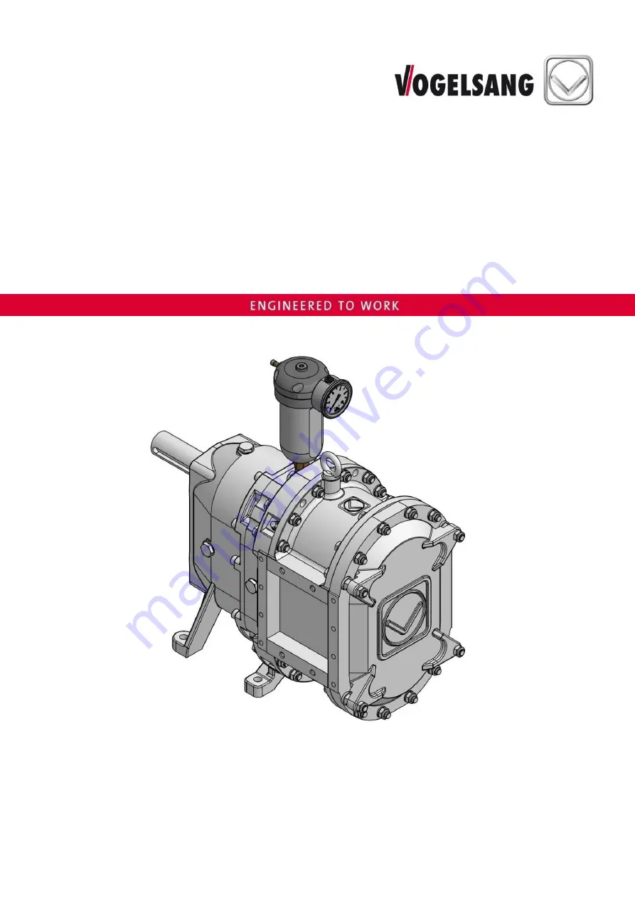
background image


2018-01-25 

*WBV.PU.002.EN VX136Q* 

WBV.PU.002.EN VX136Q 

V2.0 

1/ 74 


2018-01-25 

*WBV.PU.002.EN VX136Q* 

WBV.PU.002.EN VX136Q V2.0 


Operating Instructions 

Rotary Lobe Pump 

VX136Q 


Summary of Contents for VX136Q

Page 1: ...2018 01 25 WBV PU 002 EN VX136Q WBV PU 002 EN VX136Q V2 0 1 74 2018 01 25 WBV PU 002 EN VX136Q WBV PU 002 EN VX136Q V2 0 Operating Instructions Rotary Lobe Pump VX136Q ...

Page 2: ...ht to make technical modifications to the diagrams and information presented in this document in the event that such modifications become necessary for the enhancement of the machine 2018 Vogelsang GmbH Co KG Registered trademarks of Vogelsang In selected countries Vogelsang RotaCut HiFlo ACC CFC BioCrack XTill EnergyJet BioCut CC Serie PreMix ProTerra VarioCrop and XRipper are registered trademar...

Page 3: ...ate 14 4 Safety 15 4 1 Operator s responsibilities 15 4 2 Personnel qualification 16 4 3 Fields of activity 16 4 4 Intended use 17 4 5 General safety notes 17 4 6 Main switch maintenance and repair switch 18 4 6 1 EMERGENCY STOP shutdown main switch 18 4 6 2 Maintenance and repair switch 18 4 7 Warning and safety stickers on the machine 19 5 Transport storage 20 5 1 Transport 20 5 2 Storage 21 6 A...

Page 4: ...cartridge mechanical seal 49 8 5 Gearbox 50 8 5 1 Gear oil grade 50 8 5 2 Gear oil quantity 50 8 5 3 Gear oil inspection and change 50 8 6 Greasing of sealing prechamber 52 8 7 Oils and lubricants 53 9 Repair 56 9 1 Conversion and spare parts 56 9 2 Opening the Q cover 57 9 3 Rotary lobe change 58 9 4 How the lobe puller works 60 9 5 Change of wear plates 62 9 6 Change of cartridge mechanical seal...

Page 5: ...ig 17 Pump with pressure valve 45 Fig 18 Installation example dry buffer chamber 48 Fig 19 Flushing operation 49 Fig 20 Gear oil change 51 Fig 21 Opening closing the Q cover 57 Fig 22 Rotary lobe change 58 Fig 23 HiFlo and HiFloplus arrangement 59 Fig 24 Position of pressure disc and spring washer 60 Fig 25 Lobe puller components 60 Fig 26 Hooking puller arm into lobe 61 Fig 27 Pulling out the lob...

Page 6: ... of the machine Vogelsang does not accept any liability for damage resulting from failure to comply with these operating instructions KEEP FOR FUTURE REFERENCE Please keep the manual ready at hand to ensure easy access to the necessary information at all times Additional copies of the manual are available upon request 1 2 Presentation convention Presentation Meaning Listing Sublisting 1 2 Carry ou...

Page 7: ...is manual 1 If personal protective equipment is needed to work with and on the machine that is indicated by the following symbols Indicates that protective gloves must be worn for subsequent tasks Indicates that protective goggles must be worn for subsequent tasks Indicates that safety shoes must be worn for subsequent tasks ...

Page 8: ...these symbols and words CAUTION Refers to a dangerous situation in which failure to comply with the safety note could result in light injuries WARNING Refers to a dangerous situation in which failure to comply with the safety note could result in death or serious injuries DANGER Refers to an extremely dangerous situation in which failure to comply with the safety note will result in death or serio...

Page 9: ...connectors Chapter Pump connector On a base or without a base Chapter Base support surface for machine With the following drive options Chapter Drive Electric drive Hydraulic drive PTO drive Combustion engine drive With or without system control Chapter System control The machines listed in these operating instructions are subject to the Machinery Directive 2006 42 EC see sample printout in Chapte...

Page 10: ...th and safety requirements of the Machinery Directive 2006 42 EC in its design and construction and in the version marketed by us If a change is made to the machine without our agreement this declaration loses its validity Product Rotary lobe pump Applied harmonised standards DIN EN ISO 12100 2010 DIN EN 809 2012 The person or entity authorised to compile the technical documentation is Vogelsang G...

Page 11: ...rial specific differential pressure limits Notice Theoretical operating torque with max differential pressure and water designed for NBR elastomers ATTENTION Speed reduction for highly viscous media When using the pump for a highly viscous medium the pump speed must be reduced according to the material s viscosity to prevent the intake flow from breaking off on the suction side cavitation protecti...

Page 12: ...U PU Werobust Polyurethane vulcanised 50 C Abrasive medium Wear resistant PUR PUR Polyurethane cast 80 C Abrasive medium Highly wear resistant CSM CSM Hypalon Chloro sulfonyl polyethylene rubber 80 C Petrol oil acids alkali solutions Wear resistant acid resistant and alkali resistant FPM FPM Fluorocarbon gum 80 C Solvents salt water oil petrol acids Acid resistant and alkali resistant Steel lobes ...

Page 13: ...rical InjectionSystem The filling optimisation structure is located at the pump inlet and at the pump outlet This allows flow in either direction Injection S provides improved pump sealing with more seal lines thus allowing higher volumetric efficiency Injection A Asymmetrical InjectionSystem The filling optimisation structure is located at the pump inlet only Therefore the direction of flow is se...

Page 14: ... WBV PU 002 EN VX136Q V2 0 3 3 Name plate Fig 2 Name plate The name plate 1 contains the following details QR Code Product Design series Serial number Year of manufacture Weight Part number Address of Vogelsang GERMANY ...

Page 15: ... used must be complied with The following applies in particular The operator shall ensure that all persons who handle the machine have read and understood this manual If necessary the operator shall train personnel and inform them of possible hazards To help keep track of training we recommend creating a training log The operator shall clearly regulate and define responsibilities for transport ins...

Page 16: ...in serious injuries and property damage For this reason all activities must be performed by qualified personnel only Only persons who can be expected to perform their work reliably shall be permitted as personnel Persons whose ability to respond is impaired for example due to drugs alcohol or medication are not approved 4 3 Fields of activity The activities described in this manual may be performe...

Page 17: ...mage resulting from incorrect use Foreseeable misuse The machine is NOT intended for the following uses Potentially explosive atmospheres Operation subject to cavitation Use in the food industry without checking the specific hygiene requirements for the pump 4 5 General safety notes WARNING Risk of injury catching crushing collision due to rotating rotary lobes if the machine starts up unexpectedl...

Page 18: ...ing the pump in either direction forward or reverse until all liquid is drained out of the pump You can use drain cocks in the connectors to do this For complete emptying of the pump chamber remove the Q cover Chapter Opening the Q cover Before start up refill with fluid 4 6 Main switch maintenance and repair switch All pole disconnection must be provided for the main switch and maintenance and re...

Page 19: ...ed and must be replaced immediately if damaged or lost 1 VAU 133 2 VAU 138 3 VAU 115 Fig 3 Positions of the warning and safety labels example only the position of the stickers can vary depending on the size VAU 133 Before machine start up operating instructions must be read VAU 138 Buffer or quenching fluid tank VAU 115 Only used for pumps with a mechanical seal consisting of the material combinat...

Page 20: ...te authorisation Cranes and hoists as well as forklifts must be designed for the weight of the transport units Standing under raised loads is prohibited Have people leave the danger area Permissible transport options for the machine suspended or bolted onto a Euro pallet In the case of suspended transport of the machine Remove the buffer fluid tank or quenching fluid tank before transport Use the ...

Page 21: ...der 65 and the temperature should be between 5 C and 30 C The pump chamber can be sealed with a preservative that is compatible with the material of the lobes and gaskets The products should be protected against light especially direct sunlight and strong artificial light with a high ultraviolet component After a storage period of five years or more and before start up we recommend Checking and re...

Page 22: ...lling the pump ensure that there is easy access for maintenance work If the screw plugs for draining the gear oil and buffer or quenching fluid are not easy to reach discharge lines may be used part nos PBT 013 and or PBT 014 Ensure that the pump is installed tension free and that no tension can develop during operation either a b c d Fig 5 Installation variants a upright b horizontal c vertical f...

Page 23: ...gured for the weakest member WARNING Risk of injury from medium escaping under high pressure If the maximum pressure is exceeded Chapter Specifications parts may burst and the pumped medium may be expelled under high pressure Follow the recommendations for pipes Only use high pressure pipes on the discharge side Up to nominal diameter DN 150 PN 16 bar pipes Above nominal diameter 200 PN 10 bar pip...

Page 24: ...Suction lines whose diameter is too small may restrict the suction capability of the pump Caution risk of cavitation If the diameter of the suction pipe is too small the maximum suction height will be reduced by the loss of pressure due to pipe friction Contact us for a calculation Suction lines over 30 m must be laid with a slope of at least 2 x pipe diameter in the direction of flow ensuring tha...

Page 25: ...Chapter InjectionSystem 6 3 1 Pump with motor drive If you are using motor driven pumps with one drive shaft the flow direction is selected by determining the direction of rotation of the drive motor such as an electric motor or hydraulic motor Fig 7 Flow direction with motor drive 6 3 2 Pump with PTO drive If you are using tractor driven pumps with two drive shafts connect either the upper or low...

Page 26: ... connector has a sight glass the sight glass may burst if the pressure is too high A connector with a sight glass must be installed on the suction side The pressure may not exceed max 2 bar during reverse pumping A Sight glass Fig 9 Flow direction with pump units 6 3 4 Pumps with InjectionSystem Chapter Specifications InjectionSystem Injection S Symmetrical InjectionSystem With the symmetrical Inj...

Page 27: ...ified maximum permissible flange loads and bending moments for the pump connectors see Dimension sheet Tightening torques Hexagon head bolt M 10 10 9 steel 70 Nm Hexagon head bolt M 10 A4 70 stainless steel 40 Nm Retighten all bolts for fastening the connections after 20 operating hours and then every 2000 operating hours at least once a year ATTENTION Before installing stainless steel bolts and s...

Page 28: ...s and discomfort Install the base in a stressless manner on the support surface Retighten all screws and nuts for fastening the motor and the machine to the base after 20 operating hours and then every 2000 operating hours at least once a year After fastening the machine to the base and the base to the ground on which the machine is standing the coupling orientation must be checked and realigned i...

Page 29: ...ing must be complied with To protect the machine against damage caused by vibrations check the orientation of the coupling before start up and then every 2000 operating hours at least once a year and correct it as necessary Fig Orientation procedure If alignment errors are determined or after any blockage e g by foreign matter check the function of all parts of the drive line and readjust it if ne...

Page 30: ... repairs or troubleshooting once all the protective equipment has been re installed Check the fixed screw connection of the coupling guard after the first 20 operating hours and then every 2000 operating hours at least once a year Fig 12 Coupling guard Pos Quantity Part no Denomination Tightening torque 1 2 GZS0337 Coupling guard individual part 2 1 GZS0333 Separation mat 3 1 GZS0335 Safety plate ...

Page 31: ...ds of shutdown After the first 10 operating hours Every 2000 operating hours once per year minimum 6 5 6 Machine on hand cart WARNING Risk of crushing or concussion due to falling machine caused by insufficient stability Secure the hand cart against toppling or rolling during standstill and when the pump is in operation 6 5 7 Machine on three point base WARNING Risk of crushing or concussion due t...

Page 32: ...chnical personnel following installation in the pipe RISK OF ELECTRIC SHOCK Touching live parts leads to dangerous electrocution This can result in electric shock burns or death RISK OF ELECTRIC SHOCK The equipotential bonding shall be executed in accordance with standard EN 60204 1 In other words all metallic parts of the machine or plant must be connected electroconductively to each other or to ...

Page 33: ...36Q V2 0 33 Before start up or long term storage The seal on the vent screw if present must be removed in order to prevent overpressure build up in the gearbox and thus leakage Fig 13 Vent screw on the gearbox removing the seal ...

Page 34: ...ressure and the permissible delivery rate Connect the overflow oil line in accordance with the manufacturer s instructions Replace hydraulic hose lines that show signs of damage or ageing Only use genuine Vogelsang hydraulic hose lines The date of manufacture of the hydraulic hose line is displayed on the pressing component of the connector The period of usage for the hydraulic hose line should no...

Page 35: ...gine exhaust gases can lead to a loss of consciousness and death Never operate the engine in enclosed or poorly ventilated spaces Do not breathe in exhaust gases DANGER Fire hazard due to fuel Leaking or spilled fuel can ignite on hot motor parts and cause serious burns Only refuel when the engine is switched off Never refuel in the vicinity of open flames or ignitable sparks Do not smoke Do not s...

Page 36: ...on and make sure that the components to be installed are clean WARNING Risk of catching hands or work clothing in the rotating shaft end without cardan shaft There is a risk of injury due to accidental contact with the exposed rotating shaft end Before start up operation make sure that a suitable PTO shaft guard is installed If no suitable PTO shaft guard is present please request one from us Oper...

Page 37: ...res monitoring equipment Machines that are operated in automatic mode must be equipped with a temperature and pressure monitoring system This monitoring equipment can be obtained from us as an option Variable frequency drive operation In general rotary lobe pumps can be used in variable frequency drive operation Advantages Adaptation to operating conditions viscosity delivery rate NPSHavail Wear c...

Page 38: ...up the machine in the presence of persons who are responsible for further operation of the machine WARNING Risk of injury catching by rotating rotary lobes The pump may only start up if the inlet and outlet pipes are connected so that access to the rotating rotary lobes in the pumping chamber is not possible ...

Page 39: ...figured correctly Units should be suitable for heavy starting Is the motor connected correctly to the hydraulic lines if applicable documents provided by the motor manufacturer Buffer chamber pump gearbox Are the optional buffer chamber assemblies correctly installed Are they correctly adjusted Is the buffer chamber pressure OK if applicable Chapter Maintenance Buffer chamber Is the type of buffer...

Page 40: ...lease the buffer chamber pressure To protect against fluids spraying out carefully and slowly open the buffer chamber and the gearbox Cover the valves or screws to be removed with a cloth or similar item where appropriate 8 1 Buffer chamber In the following chapters we describe the following possible buffer chamber assemblies 1 Chapter Pressurisable buffer fluid tank 2 Chapter Depressurised quench...

Page 41: ...e tank about one quarter full when delivered the buffer chamber is already filled 4 Close the tank and use a manual air pump or a compressed air supply outlet to set the required tank pressure Topping up buffer fluid maintenance and inspection Fig Buffer fluid tank and Filling draining the buffer chamber 1 Release the pressure in the buffer chamber via the valve on the tank 2 Open the tank undo th...

Page 42: ...2 WBV PU 002 EN VX136Q V2 0 Upright installation Horizontal installation Vertical installation Suspended installation Fig 15 Draining filling the buffer chamber 1 Screw plug A Filling 2 Buffer fluid tank B Draining ...

Page 43: ... and should not exceed 10 bar with a double mechanical seal Rotary lobe change and Cartridge mechanical seal change Before a rotary lobe and Cartridge mechanical seal change reduce the tank pressure and increase it again after changing Trouble indication Possible indications of trouble in the sealing system after the running in period Severe contamination of the buffer fluid in the tank Buffer flu...

Page 44: ...hing fluid tank and the topping up of quenching fluid is as described in Chapter Pressurisable buffer fluid tank The instructions for pressurising the tank do not apply in the case of buffer chamber assembly depressurised quenching fluid tank Please also observe the Trouble indication and Buffer fluid properties in Chapter Pressurisable buffer fluid tank 1 Screw plug installation tightening torque...

Page 45: ...er fluid leave a buffer of air above it about 1 cm distance between the oil level and the bearing seal housing Fig Pump with pressure valve The air buffer prevents the buffer chamber fluid from escaping through the pressure valve due to thermal expansion 1 Pressure valve A Air buffer B Oil level Fig 17 Pump with pressure valve 8 1 4 Plugs The buffer chamber assembly with plugs is used only for spe...

Page 46: ...ct with the medium are made of stainless steel Guideline depending on the buffer chamber assembly Chapter Buffer chamber assemblies 8 1 7 Buffer or quenching fluid inspection and change Buffer fluid or quenching fluid Check After the first 20 operating hours Every 200 operating hours Electronic buffer chamber monitoring is possible Ask us replace Every 2000 operating hours When there is severe con...

Page 47: ... fluid tank or pressure valve depressurise the buffer chamber before draining or cleaning 2 Remove the buffer chamber assemblies 3 Undo the lower screw plug 1 Fig Filling draining the buffer chamber or Fig Pump with quenching fluid tank and drain the buffer or quenching fluid from the buffer chamber 4 If there is severe contamination clean the buffer chamber 5 Screw the lower screw plug back in ti...

Page 48: ... plug from the vent screw 5 Fig Installation example dry buffer chamber and completely fill the pump chamber with fluid Combination of mechanical seal rings in this sealing system Type of construction block ring Mating materials AISI 304 AISI 316 Ti tungsten carbide coated carbon Installation Fig Installation example dry buffer chamber Connect tank 3 with connecting pipe 4 at the bottom of the buf...

Page 49: ...hing pressure and volume flow Fig Flushing operation connection example for flushing pressure and volume flow adjustment Adjusting the flushing pressure The flushing pressure can be adjusted and monitored with a pressure gauge The flushing pressure should be about 0 5 bar higher than the average pressure in the pump Flushing pressure 0 5 bar pressure on the suction side pressure on the discharge s...

Page 50: ...dge mechanical seals Note with this alternative flushing operation A possible defect cannot be assigned to the single cartridge mechanical seal Possible impurities of the cartridge mechanical seal rinsed for the first time can get into the subsequent mechanical seal 8 5 Gearbox 8 5 1 Gear oil grade We recommend the oils listed in Chapter Oils and lubricants 8 5 2 Gear oil quantity 2 litres 8 5 3 G...

Page 51: ...d installation Fig 20 Gear oil change 1 Screw plug A Filling 2 Magnetic screw plug B Draining 3 Grease nipple C Checking The screw plug 1 must be at the top and the magnetic screw plug 2 must be at the bottom Tightening torque ut 39 mod_1259315210400_6 doc 141472 Tightening torque for installing the screw plugs 60 Nm ...

Page 52: ...g and impairing the function of the mechanical seal ATTENTION A regular lubrication interval prevents the lubrication channel from clogging To ensure effective distribution of the lubricant always lubricate while the machine is running and not when it is stationary Lubricating grease type We recommend the lubricating grease listed in Chapter Oils and lubricants Lubricating grease quantity 5 shots ...

Page 53: ...60 C DIN ISO 2592 Pour point 42 C DIN ISO 3016 Damage loading step 12 Water hazard class Slightly hazardous to waters When using BSS0021 oil for the pump gearbox the maintenance interval for checking and changing the gear oil may be doubled Chapter Maintenance plan Part number BSS 010 Description Medical white oil water white non fluorescent tasteless and odourless mixture of hydrocarbons Trade na...

Page 54: ... 210 C DIN ISO 2592 Pour point 24 C DIN ISO 3016 Damage loading step 12 Water hazard class Slightly hazardous to waters Part number BSS 016 Description Biodegradable environmentally friendly multigrade hydraulic oil based on rape seed oil as per ISO 15308 type HETG Trade name Fuchs Hydraulic oil 40 N Characteristics Test acc to ISO VG 46 DIN 51519 Viscosity index 220 DIN ISO 2909 Kinematic viscosi...

Page 55: ... gear oil based on selected polyglycols PAG Trade name Fuchs Renolin PG 46 Characteristics Test acc to ISO VG 46 DIN 51519 Viscosity index 203 DIN ISO 2909 Kinematic viscosity at 40 C 46 mm s DIN 51562 Flash point 240 C DIN ISO 2592 Damage loading step 12 Water hazard class Slightly hazardous to waters 5 Lubricant for pump grease nipples Part number BSS 002 Description Lithium soap grease with a m...

Page 56: ...r her staff about any potentially hazardous substances in working materials or media ATTENTION Before installing stainless steel bolts and stainless steel nuts Clean threads and contact surfaces Apply anti seize paste part no BKL 014 BAS 001 evenly and in sufficient quantity to the screw head face and bearing face and to the thread using a brush or filling knife etc to avoid seizing of stainless s...

Page 57: ...in the pump as much as possible Attention Any remaining fluid will flow out of the machine when the Q cover is dismounted 4 Depressurise the buffer chamber if necessary Chapter Buffer chamber 5 Undo hexagon nuts 1 on the Q cover 2 6 Remove Q cover and remove the O ring 3 Fig 21 Opening closing the Q cover 1 Hexagon nut washer 2 Q cover 3 O ring ...

Page 58: ...s in pairs Chap How the lobe puller works 4 Before installing the new lobes thoroughly clean the contact surfaces of lobes and seal components 5 Install the new rotary lobes in reverse order Fig Arrangement of HiFlo and HiFloplus Notice solid material lobes When assembling solid material lobes fit an O ring 12 on the gearbox side of each lobe When installing two lobe pairs also fit an O ring 11 be...

Page 59: ...160 Nm then loosen it and tighten again with 140 Nm 7 Close the Q cover Chap Closing the Q cover 8 Adjust the pressure in the buffer chamber if necessary Chap Buffer chamber HiFloplus HiFloplus rotary lobes in contrast to HiFlo rotary lobes have a second groove The groove which in the arrangement HiFloplus is not to be used is marked in red HiFlo HiFloplus Fig 23 HiFlo and HiFloplus arrangement L ...

Page 60: ...lled off as simultaneously as possible VX136 70 105Q part no PBA B001 TK VX136 140 210Q part no PBA B001 TL Alternatively Combination tool for lobe change and Cartridge mechanical seal change of all VX136Q pump sizes part no PBA B033 T1 1 Hexagon head bolt 2 Puller arm 3 Pressure rod Fig 25 Lobe puller components 1 Undo the four hexagon head bolts 1 so that the puller arms 2 can be moved 2 Hook th...

Page 61: ...g out the lobes with lobe puller Fig 26 Hooking puller arm into lobe Fig 27 Pulling out the lobes with lobe puller Maintenance instructions for lobe puller Regularly check the puller arms for wear and breakage Keep the threaded bolt in the pressure rod clean at all times and lubricate it regularly ...

Page 62: ...otary lobes the correct installation position of the wear plate must be observed during installation Fig Installation position of the curved wear plates Tightening torque Wear plate screws 40 Nm 1 Wear plate on the gearbox 2 Wear plate on the cover 3 Hexagon head screw with microencapsulation Fig 28 Installation position of the curved wear plates ...

Page 63: ...cartridge mechanical seal carefully remove the burrs on the keyways and clean the cartridge mechanical seal seat in the housing 11 Push new cartridge mechanical seal onto the shaft Carefully oil the outer O rings on the seal carrier pos 5 in Fig b before installation Attention Do not use mineral oil or grease for O rings made of EPDM Use glycol as an alternative 12 If a circulation system is prese...

Page 64: ...X136Q V2 0 a b c Fig 29 Cartridge mechanical seal on the gearbox 1 Set screw 4 O ring bearing seal housing 2 Cylinder head bolt 5 O ring seal carrier 3 Hexagon head bolt A Installation tool included in tool with part no WKZ0456 ...

Page 65: ...he top clearance must be at least as large as one adjustment 1 Remove the Q cover Chapter Opening the Q cover 2 Undo the connectors and bolts on the pump housing segments 3 Shift the spring pins of the upper and lower pump housing segments to both sides Fig Adjustment of pump housing segments 4 Before installation of the pump housing segments apply flange sealant set a flat gasket in place and coa...

Page 66: ...PFL B009 5 mm with PFL B009 T2 4 7 mm On cover side Replace the wear plate PFL B002 4 mm with PFL B002 T2 3 7 mm Increasing the gap by installing shims Gap increase 0 2 mm on the Q cover Put one new shim 10 x 16 x 0 2 NUS 062 on each of the four distance nuts of the Q cover Gap increase 0 2 mm on the gearbox 1 Put one new shim 60 x 75 x 0 2 NUS 061 on each shaft in front of the first lobe 2 In add...

Page 67: ...of rotation Change the pump s direction of rotation Flow direction C Pipe causing pump housing warping Check the orientation of the pipe to the pump If necessary provide a compensator or secure the pipe Installation in pipes D Leakage in the suction pipe Check the suction side pipe system for leakage Gas formation Vent the suction pipe and pump chamber top up fluid E Suction pipe clogged Check the...

Page 68: ...ffer chamber Maintenance R Differential pressure too high Reduce differential pressure Specifications S Medium viscosity above the nominal value Reduce speed Increase medium temperature Intended use T Medium viscosity below the nominal value Increase speed decrease medium temperature replace wear parts Repair Gaps too large Reduce gaps Chapter Reducing the starting torque but with the procedure re...

Page 69: ... undoing screws and bolts 3 Drain working materials Drain the gear oil from the pump gearbox Observe notices and safety notes Chapter Gear oil inspection and change Drain the buffer or quenching fluid from the buffer chamber Observe notices and safety notes Chapter Draining and cleaning the buffer chamber 4 Drain the pump and remove residual medium Observe notices and safety notes when opening the...

Page 70: ...70 WBV PU 002 EN VX136Q V2 0 Maintenance and service plan ...

Page 71: ... with a mechanical seal with SiC SiC material combination that are not put into operation immediately needs to be turned at least one revolution about every two months 12 2 Maintenance intervals ATTENTION Carefully observe the following maintenance intervals and document them in the service plan Chap Service plan Before start up Check pump motor coupling orientation base C Before start up and befo...

Page 72: ...coupling guard base C Check pump motor coupling orientation base C Change the buffer or quenching fluid Change the gear oil 12 3 Additional maintenance intervals for pumps with belt drive See also Technical information for belt drives TINF PU 020 xx Before start up and after long periods of shutdown Check belt tension and belt orientation After 0 5 to 4 operating hours Check belt tension Every 6 m...

Page 73: ...Retighten the screws for the base or machine attachment Check fixed screw connection of coupling guard base C Check pump motor coupling orientation base C Lubricate grease nipples Check the buffer or quenching fluid Check the buffer or quenching fluid Check gear oil Change gear oil On pumps with belt drive Others maintenance instructions Operating hour meter Total capacity Date Name Sign ature Che...

Page 74: ...owenien VGS TECH GREGOR TURSIC S P vogelsang info Dänemark Vogelsang A S vogelsang as dk Malaysia Vogelsang Malaysia vogelsang info Schweden Vogelsang Sverige AB vogelsang se Deutschland Niederlassung Ost Vogelsang Lutherstadt Eisleben vogelsang info Mexico Vogelsang De México S de R L de CV vogelsang mx Spanien Vogelsang S L vogelsang es Finnland Vogelsang Oy vogelsang fi Niederlande Bos Benelux ...

Reviews: