Asse mbl y
34
WBV.PU.002.EN VX215QD V2.0
6.6.2
Hydraulic drive
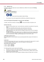
Connection to the energy supply may only be established by qualified technical personnel
following
installation in the pipe.
WARNING
Risk of infection from hydraulic oil!
Leakages can occur due to seal faults.
•
Personnel must wear suitable protective clothing.
•
The connection to the power supply must be established by qualified technical personnel.
In the event of injuries with hydraulic oil, consult a doctor immediately!
In addition, also read and observe the following:
"Technical information for hydraulic motor"
Hydraulic hose lines
Pos : 138 /WBV/Pumpen/ Warnhinweis e/Maschi nengefahr/H ydrauli kmotor en bei Pumpen mi t hydr aulisc hem Antri eb @ 61\ mod_1317991178246_6.doc x @ 320128 @ @ 1
•
Before connecting hydraulic hoses, read and follow the manufacturer’s specifications for hydraulic
motors.
•
Observe the permissible hydraulic pressure and the permissible delivery rate.
•
Connect the overflow oil line in accordance with the manufacturer's instructions.
•
Replace hydraulic hose lines that show signs of damage or ageing. Only use genuine Vogelsang
hydraulic hose lines.
•
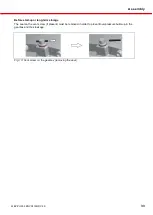
The date of manufacture of the hydraulic hose line is displayed on the pressing component of the
connector. The period of usage for the hydraulic hose line should not exceed 6 years (although 5
years is recommended), including a possible storage period of no more than 2 years.
Pos : 139 /WBV/Pumpen/ Warnhinweis e/Hinweis/ Anschli eß en H ydr auli kmot or @ 61\ mod_1317734946024_6. doc x @ 318350 @ @ 1
Installing two hydraulic motors
When two hydraulic motors are installed, they are operated parallel and the torques of both motors are
added.
Pos : 140 /WBV/Pumpen/ Warnhinweis e/Maschi nengefahr/ St euergerät - H ydrauli kmotor @ 86\ mod_1354611286450_6. doc x @ 450235 @ @ 1
Control unit
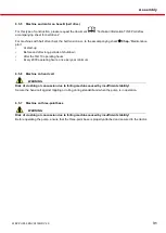
In the event of high hydraulic motor speeds, never suddenly set the control unit to "lock position" in order to
avoid pressure peaks. Whenever possible, switch from "operation" to "floating position".
Speed measurement (cam wheel)
Pos : 138 /WBV/Pumpen/ Warnhinweis e/Maschi nengefahr/H ydrauli kmotor en bei Pu mpen mi t hydr aulisc hem Antri eb @ 61\ mod_1317991178246_6.doc x @ 320128 @ @ 1
ø 50 mm
part no. PBT0974
ø 40 mm
part no. PBT0848
Pos : 139 /WBV/Pumpen/ Warnhinweis e/Hinweis/ Anschli eß en H ydr auli kmot or @ 61\ mod_1317734946024_6. doc x @ 318350 @ @ 1
The following activities must be carried out for assembly:
1.
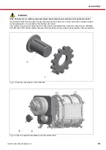
Place the cam wheel (1) on the shaft end (2) (
Fig
. "Place the cam wheel on the shaft end").
2.
Oil and press the speed measurement (3) into the free hollow shaft (4) (
Fig
. "Press the speed
measurement into the hollow shaft").
3.
Protect the cam wheel from contact, taking the following warnings and safety notes into account.

