Page 8
/
NORSEMAN™ 1500/2500 FuRNAcE
VGZ-018 / 051809.0
AssEMblY iNstRUctioNs
Yo u r N O R S E M A N ™ Wa r m A i r F u r n a c e
requires the following items to be assembled or installed
by the furnace installer:
Feed Door Pull Handle/Thermostat Assembly
Feed Door Locking Handle
Blower(s) and Blower control
Electrical connections
1. Remove all parts from inside the furnace and
inspect for damage, including the firebrick as
some breakage could occur during shipment.
Do not operate furnace with broken or miss-
ing fire box bricks. Replace damaged bricks
before operating furnace.
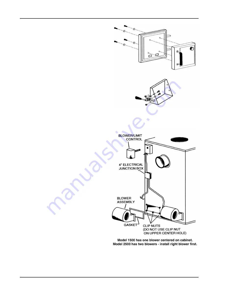
2. Assemble the feed door pull handle as shown in
figure 4. Install thermostat assembly and cover as
shown.
3. Align thermostat control knob with flat on thermostat
control shaft and press onto shaft (figure 4).
4. Attach feed door locking handle as shown in
figure 5 with screws and nuts provided.
Note: Slotted holes are for adjustment of handle.
Adjust handle until pressure is required to lock feed
door.
5. Install Blower/Limit control on rear of furnace
cabinet as shown in figure 6 using three (3) sheet
metal screws.
6. Remove blower(s) from carton(s). Attach the flex-
ible conduit/wire assembly to the blower(s) before
mounting.
7. Remove junction box cover and take out the mount-
ing hardware package. Position clip nuts to furnace
housing around blower opening as shown in figure
6. On Model #2500, install the right (when facing
rear of furnace) blower first. Install the blower(s)
with gasket using 1/4-20 x 3/4˝ bolts.
8. Secure the 4 inch square electrical junction box to
the black bracket on the rear of the stove using two
(2) sheet metal screws.
9. Wire blower according to the wiring diagram shown
in figure 7/8. On model 2500, wire right side blower
first (see figure 7). Replace junction box cover when
complete. use 16 ga. AWG rated for 90° c min.
10. check operation of shaker grates with grate handle
before loading fuel in furnace.
Fig. 4 – Door/Handle/Thermostat Assembly
Fig. 5 – Feed Door Handle Assembly
Fig. 6 – Blower Assembly


