background image

Page 10 

TR001 DEFENDER™


www.vogelzang.com


VGZ-026 / 20120306.0

CHIMNEY CONNECTIONS continued …

or a knowledgable inspector. Consult your insurance 
company if you cannot find a qualified expert.

CAUTION: NOT ALL FIREPLACES ARE SUIT-
ABLE FOR CONVERSION TO ACCOMMODATE 
A WOOD STOVE. CHECK WITH A QUALIFIED 
EXPERT.

Many prefabricated fireplaces are of the “zero-

clearance fireplace” category. These consist of mul-
tilayered metal construction. They are designed with 
enough insulation and/or air cooling on the base, back 
and sides so they can be safely installed in direct con-
tact with combustible floors and walls. Although many 
prefabricated fireplaces carry endorsements from na-
tionally recognized organizations for use as fireplaces, 
they have not been tested for connection to wood stove 
heaters. Connecting a stove to such a device will void 
the manufacturer’s warranty.

Venting a stove directly into a fireplace does not 

meet code and should not be attempted. (This consti-
tutes connection to another appliance - the fireplace.) 
The stove warranty will be void with such an installation. 
Do not create a hazard in your home by connecting in 
this manner.

FIREPLACE INSTALLATION

Directly connecting the stovepipe into the existing 

masonry chimney (figure 10 “Type A” Fireplace Conver-
sion) of the fireplace is the only approved method of 
installation. This is a complicated and involved process 
and to insure safety should only by done by a qualified 
installer.
1.  An entry hole must be cut through the masonry and 

tile liner with minimal damage to the liner. At least 8” 
of liner must remain below the entry position. When 

3.  Secure the thimble with refractory mortar. The 

thimble should be surrounded by 12” of solid unit  
masonry brickwork or 24” of stone.

4.  Install the stovepipe into the thimble as far as pos-

sible without extending past the flue lining (see 
figures 4 & 6 on pages 6 & 7). 

5.  A small airspace (about 1/2”) should remain 

between the stovepipe and thimble to allow for 
expansion of the pipe. Seal this airspace with high-
temperature caulking or ceramic wool.

6.  Secure and seal the damper in the closed posi-

tion using high-temp caulking, ceramic wool, or 
furnace cement. Also check to see if the chimney 
has a cleanout. If it does, make sure it is closed and 
sealed as well. A leaky cleanout will greatly reduce 
draft efficiency.
If you have any questions regarding venting your 

stove, contact the manufacturer or contact the National 
Fire Protection Association (NFPA) and request a copy 
of the latest editions of NFPA Standard 211 and NFPA 
Standard 908. Their address is:

 Battery March Park, Quincy, MA 02269.

FIG. 10 - Fireplace Conversion

locating the stove and stovepipe, all 
minimum clearances must be ob-
served from combustible surfaces 
including mantels, combustible trim-
work, ceilings and walls. Positioning 
the center of the stove pipe entry into 
the chimney 24” below the ceiling 
should insure proper clearance for 
a 6” stovepipe.

2.  Install a metal or fire clay (5/8” mini-

mum thickness) thimble. Make sure 
the thimble is flush with the inner 
surface of the chimney liner and does 
not protrude into the flue (see figure 
4 on page 6).

Summary of Contents for DEFENDER TR001

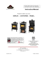
Page 1: ...PROPERLY INSTALLED A HOUSE BUILDING FIRE MAY RESULT FOR YOUR SAFETY CONTACT LOCAL BUILDING OR FIRE OFFICIALS ABOUT PERMITS RESTRICTIONS AND INSTALLATION REQUIREMENTS FOR YOUR AREA Vogelzang International Corporation 400 West 17th Street Holland Michigan 49423 www vogelzang com Phone 1 616 396 1911 Fax 1 616 396 1971 DEFENDER HIGH EFFICIENCY AIR TIGHT WOODSTOVE EPA Certified 4 21grams hr Model TR00...

Page 2: ...R APPLIANCE 9 DO NOT CONNECT A WOOD BURNING STOVE TO AN ALUMINUM TYPE B GAS VENT This is not safe Use approved masonry or an Underwrit ers Laboratories Listed UL 103 HT US ULC S629 CDN Residential Type and Building Heating Ap pliance Chimney Use a 6 152mm diameter chim ney that is high enough to give a good draft See specifics in Chimney Connections instructions 10 Be sure that your chimney is saf...

Page 3: ... height or in such a manner that it creates a hazard when opening the door 28 NEVER LEAVE THE STOVE UNATTENDED with door open Always close the door after ignition 29 DO NOT CONNECT TO OR USE IN CONJUNC SAFETY INSTRUCTIONS continued TIONWITH ANY AIR DISTRIBUTION DUCTWORK UNLESS SPECIFICALLY APPROVED FOR SUCH INSTALLATIONS 30 A WOOD BURNING STOVE MUST NEVER BE INSTALLED IN A HALLWAY OR NEAR A STAIR ...

Page 4: ... to obstruct air flow Use four screws provided to fasten the blower to rear heat shield 2 Route the power cord away from stove Do not al low the power cord to touch any hot surfaces Keep power cord at least 12 from stove surfaces 3 Once stove is positioned plug power cord into a grounded 120v outlet 1 The stove must be placed on solid concrete solid masonry or when installed on a combustible floor...

Page 5: ... the stove connector stove pipe and corner clearanc es using the illustrations in figures 1 3 and your local building codes or fire protection ordinances NOTE Drywall faced with brick or stone must be considered a combustible surface 6 Do Not install this stove in a mobile home Manufactured Home trailer or Tent NO EXCEPTIONS HUD Federal Standard 24 CFR Ch xx 7 The clearances provided are minimum d...

Page 6: ...ove and radiates heat more evenly Check to see that all firebricks are in their correct positions and have not become misaligned during shipping or assembly If removed for ease of locating stove firebrick must be replaced before firing See diagrams fig 4a 4c for proper positioning CAUTION NEVER OPERATE STOVE WITH MISSING OR CRACKED FIRE BRICKS Fig 4a Step 1 Bottom Firebrick Installation A A C B A ...

Page 7: ...These provide a better seal 7 The connector pipe must not pass through an at tic or roof space closet or any concealed space or floor ceiling wall or combustible construction See Chimney Connector Systems Clearances page 11 A UL 103 HT Listed U S or ULC S629 CANADA chimney must be used from the first penetration of ceiling or wall to the chimney cap Never use single wall connector pipe as a chimne...

Page 8: ...nufacturer cannot be held responsible for external factors leading to less than optimal drafting Should you have a problem with inadequate draft you should contact a licensed heating and cooling con tractor for assistance in solving the problem IMPORTANT Installation Points 1 Size chimney flue to stove collar This stove requires a 6 diameter flue 2 Never connect this unit to a chimney serving an o...

Page 9: ...tractor consult your local yellow pages for chimney installation Manufactured chimney with the proper required UL listing is available from most home centers hardware stores and HVAC supply stores If you have access to the internet you may wish to view chimney manufacturers information on line See www duravent com www selkirkinc com or www mtlfab com VENTING TO EXISTING FIREPLACE In some instances...

Page 10: ...try hole must be cut through the masonry and tile liner with minimal damage to the liner At least 8 of liner must remain below the entry position When 3 Secure the thimble with refractory mortar The thimble should be surrounded by 12 of solid unit masonry brickwork or 24 of stone 4 Install the stovepipe into the thimble as far as pos sible without extending past the flue lining see figures 4 6 on ...

Page 11: ...ch of glass fiber insulation Opening shall be covered and thimble supported with a sheet steel support minimum 24 gauge in thickness D Chimney Section Pass through Solid insulated listed factory built chimney length with an inside diameter 2 inch larger than the chimney con nector and having 1 inch or more of insulation serving as a pass through for a single wall sheet steel chimney connector of m...

Page 12: ... open slightly DO NOT LEAVE STOVE UNATTENDED WITH DOOR OPEN 5 Add large pieces of wood as the fire progresses being careful not to overload Do not fill firebox beyond firebrick area An ideal coal bed of 1 2 should be established t achieve optimum perfor mance 6 This unit is designed to function most effectively when air is allowed to circulate to all areas of the firebox An idea rake a slight 1 to...

Page 13: ... resume and wood is sufficiently ignited The basic rule of thumb is closed low half way open medium and fully open high ADDING FUEL Add small amounts of fuel each hour or so instead of piling large quantities of fuel at one time This will insure a more complete combustion process and less buildup of tars soot or creosote will occur in the chimney 1 When refueling adjust air inlet control to the fu...

Page 14: ...se impact the glass When closing doors make sure that logs or other objects do not protrude to impact the glass 3 Do not build fires against or that might fall against the glass 4 Do not clean the glass with materials that may scratch or otherwise damage the glass Scratches on the glass can develop into cracks or breaks dur ing operation 5 Never attempt to clean the glass while the unit is hot all...

Page 15: ...himney connector should glow red reduce the fire by clos ing the inlet air control and immediately call the fire department CAUTION A CHIMNEY FIRE MAY CAUSE IGNI TION OF WALL STUDS OR RAFTERS WHICH WERE ASSUMED TO BE A SAFE DISTANCE FROM THE CHIMNEY IF A CHIMNEY FIRE HAS OCCURRED HAVE YOUR CHIMNEY IN SPECTED BY A QUALIFIED EXPERT BEFORE USING AGAIN A fire in the firebox may be smothered by pouring...

Page 16: ...me 1 18 Door Glass 1 19 Gasket 3 8 Fiberglass Glass 1 20 Retainer Glass 1 21 Screws Glass Retainer 8 22 Gasket 3 8 Fiberglass Door 1 23 Hinge Pin 2 24 Nuts for legs 4 25 C Cast Fiber Board 9 x9 x5 8 2 1 Legs 4 2 Heat Sheild 1 3 Handle Slide Draft Spring 1 4 Nickle Trim Top Plate 1 5 Nickle Trim Hearth 1 6 Air Tube Rear 1 7 Air Tube Middle 1 8 Air Tube Front 1 9 Retainer Pins Air Tube 3 10 Z Bar Ba...

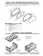
Page 17: ...A B A A B A C C A A A C B A A B A A B A A B Firebrick Sides Four 4 A Size Two 2 B Size Firebrick Back Two 2 A Size Two 2 C Size Fire Brick Dimensions A Size 9 x41 2 x11 4 B Size 9 x23 4 x11 4 C Size 9 x31 4 x11 4 A A C B A A B Firebrick Bottom Four 4 A Size Two 2 B Size One 1 C Size FIREBRICK TR001 DEFENDER Part No Description Qty 15 Door Assembly complete 1 16 Handle Assembly complete 1 17 Door F...

Page 18: ...NDER BLOWER OPTION NOTICE ANY REPLACE MENT WIRING MUST HAVE EQUIVALENT INSULA TION AND TEMPERATURE RATING 105 C CAUTION MOVING PARTS CAN CAUSE INJURY DO NOT OPERATEWITH COVER REMOVED DANGER SHOCKHAZARD DISCONNECT POWERSOURCEBEFOREINSTALLATION AND WHENEVER SERVICING BLOWER ASSEMBLY ...

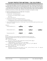
Page 19: ...or protector a Use formulas in step 1 above to calculate R value of proposed material s b For multiple layers add R values of each layer to determine overall R value 3 If the overall R value of the floor protector system is equal to or greater than the floor protector specifications given the alternate is acceptable Definitions Thermal conductance C BTU W hr ft2 F m2 K Thermal conductivity k Btu i...

Page 20: ...ES IN HIM SHALL NOT PERISH BUT HAVE ETERNAL LIFE JOHN 3 16 MADE IN CHINA This Vogelzang heating appliance is safe when installed properly and will provide you with years of service However always exercise good judgement when you are using this stove You are dealing with FIRE Fire is inherently dangerous and must be treated with respect Stay warm and in good health Respectfully yours SteveVogelzang...

Reviews: