8
10'
2' MIN.
3' MIN.
6" CHIMNEY CONNECTOR
6" ELBOW
6" SOLID DAMPER
6" BAROMETRIC
DRAFT REGULATOR
REFER TO CHIMNEY
MANUFACTURER'S
INSTRUCTIONS AND
PARTS.
Chimney Connection
MASONRY CHIMNEY
Before using an existing masonry chimney, clean the chimney
and inspect the
fl
ue liner to be sure it is safe to use. Make repairs
before attaching the furnace. The connector pipe and
fi
ttings you
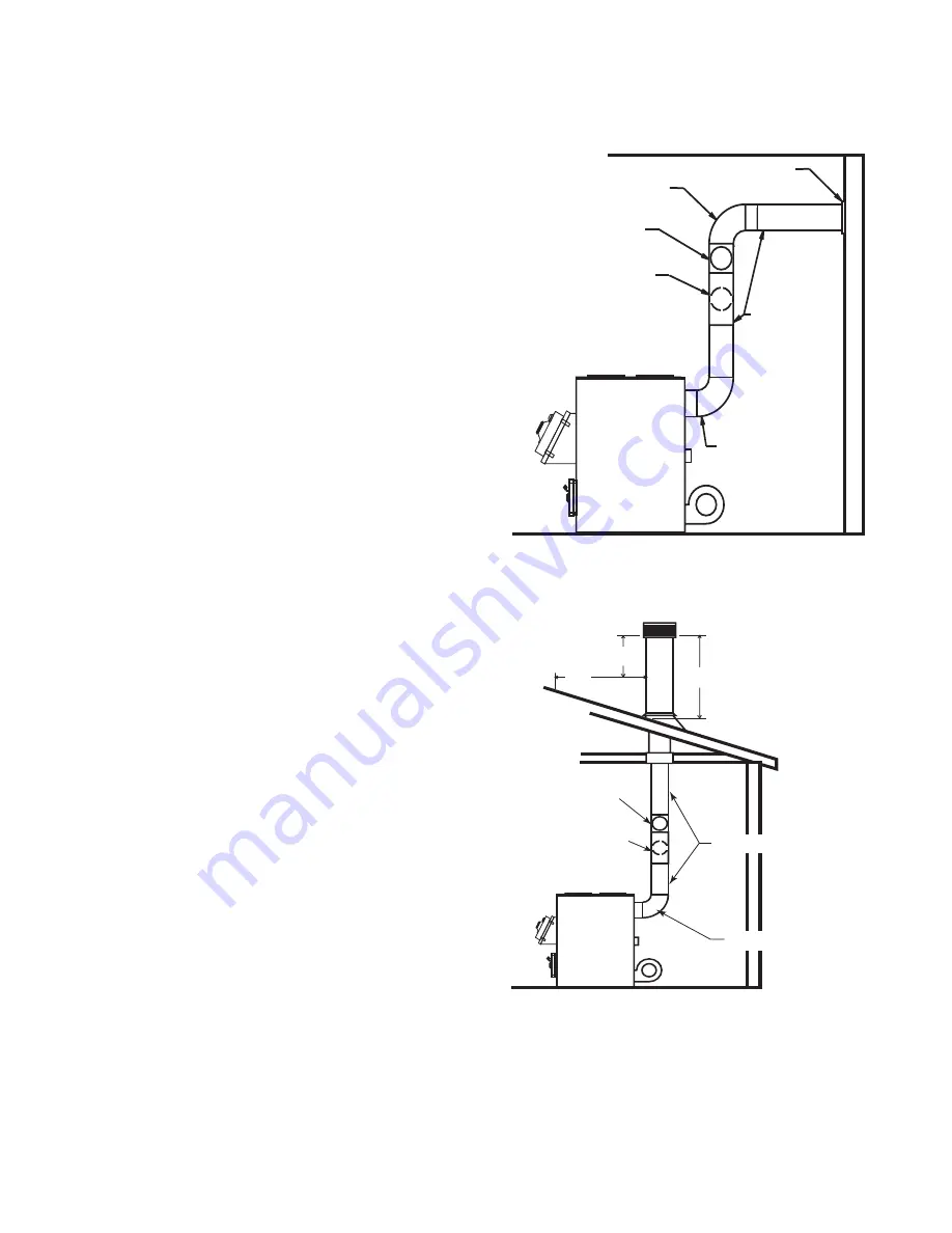
will need to connect directly to a masonry chimney are shown.
The chimney connection should be as short as possible.
If the connector pipe must go through a combustible wall be-
fore entering the masonry chimney, consult a quali
fi
ed mason
or chimney dealer. The installation must conform to local
fi
re
codes, and N.F.P.A. 211.
DO NOT CONNECT THIS FURNACE TO A CHIMNEY
FLUE SERVING ANOTHER APPLIANCE.
The chimney used for a furnace must not be used to ventilate the
cellar or basement. If there is a cleanout opening at the base of
the chimney, close it tightly.
LISTED FACTORY BUILT CHIMNEY
Carefully follow chimney manufacturer's instructions. Use only a
Listed Residential Type or Building Heating Appliance Chimney.
If your chimney starts at the ceiling (Fig. 7), you will need enough
6" pipe to reach the ceiling.
The top of the chimney must be at least 3 feet above the roof
and be at least 2 feet higher than any point of the roof within 10
feet (Fig. 7).
IMPORTANCE OF PROPER DRAFT
Draft is the force which moves air from the appliance up through
the chimney. The amount of draft in your chimney depends on the
length of the chimney, local geography, nearby obstructions and
other factors. Too much draft may cause excessive temperatures
in the appliance and may damage. Inadequate draft may cause
backpuf
fi
ng into the room and ‘plugging’ of the chimney.
“Inadequate draft will cause the appliance to leak smoke into the
room through appliance and chimney connector joints.”
“An uncontrollable burn or excessive temperature indicates
excessive draft.”
Take into account the chimney’s location to insure it is not too
close to neighbors or in a valley which may cause unhealthy or
nuisance conditions.
6" SOLID DAMPER
6" BAROMETRIC
DRAFT REGULATOR
THIMBLE
6" ELBOW
6" CHIMNEY
CONNECTOR
6" ELBOW
NON-COMBUSTIBLE WALL
Figure 6
Figure 7
Summary of Contents for VG1500
Page 6: ...6 Dimensions Of Furnace Figure 2 Models VG2500 Figure 1 Model VG1500 ...
Page 26: ...26 CENTRAL INSTALLATION ADD ON INSTALLATION ...
Page 28: ...28 INSTALLATION D INSTALLATION E ...
Page 29: ...29 INSTALLATION F INSTALLATION G ...
Page 30: ...30 INSTALLATION H TOP VIEW FRONT VIEW ...
Page 31: ...31 Notes ...
Page 32: ...32 Notes ...
Page 33: ...Notes ...


