background image

2

INTRODUCTION

Thank You for your purchase of a Vogelzang Wood/Coal 
Burning Gravity Style (Up-Flow) Furnace. Your decision 
to buy our Furnace was undoubtedly reached after much 
careful thought and consideration. We are very proud you 
chose this furnace and trust you will receive the comfort 
and economy that others realize when heating with a Vo-
gelzang product.
Your dealer is important in your experience with the fur-
nace not only with the purchase, but for recommendations 
for professional installation in your home. The quali

fi

 ed 

professional installer has been expertly trained in solid-
fuel furnace installation to assure the safety and comfort 
for your family while saving you money. 

IMPORTANT

Before installing and using your furnace, please read the 
following pages thoroughly and carefully. If you follow the 
instructions, your furnace will give you safe and more de-
pendable service for years to come.

•  First step: Check your local codes. This installation 

must comply with their rulings.

•  Do Not install this furnace in a mobile home or trailer.• 

Always have a smoke or ionization detector and a CO 
detector installed in your home.

•  To prevent injury or damage, do not allow anyone who 

is unfamiliar with the furnace to operate it.

•  This furnace must be installed ONLY in the prescribed 

manner shown in illustrations 1, 2, or 3 under the In-
stallation Examples in this manual. It is NEVER to be 
installed as a counter-

fl

 ow or down-draft furnace, or 

in any manner wherein the heated air is directed in a 
downward 

fl

 ow into the home or toward to an existing 

central furnace.

•  NEVER INSTALL outside the home.
•  Spend adequate time with your furnace to become well 

acquainted with the different settings and how each 
will affect its burning patterns. It is impossible to state 
just how each setting will affect your furnace because 
of the variations in each installation.

DISCLAIMER NOTICE

The BTU ranges and heating capacity speci

fi

 cations  are 

provided as a guide and in no way guarantee the output 
or capacity of this unit. The actual BTU output depends 
on the type of fuel being burned and its conditions, the 
thermostat setting, the draft adjustment and the chimney 
to which the unit is attached. The actual area that this unit 
will heat depends on factors such as the conditions of the 
building, heat loss, type of construction, amount of insu-
lation, type of air movement, the location of the unit and 
more importantly the duct work and return air facility.

Warning:

Do not alter this appliance in any way other than speci

fi

 ed 

in these instructions. Doing so may void your warranty.

LOCATING YOUR FURNACE

The furnace is to be installed maintaining the clearances 
speci

fi

 ed in the following illustrations.

Do not place the furnace directly on a combustible 

fl

 oor. If 

you are placing it on a combustible 

fl

 oor, an approved 

fi

 re 

retardant material, equivalent to 3/8” UL Listed millboard, 
measuring 41 x 72 should be placed under the unit. The 
material must extend at least 16 inches beyond the front 
of the unit and 8 inches on either side of the fuel loading 
door opening. It must also extend underneath the chimney 
connector and to each side of the connector by at least 2 
inches.

CLEARANCES

REDUCED CLEARANCES

NFPA guidelines and most codes permit reduced clear-
ances to combustible walls and ceilings if adequate pro-
tection is added. A common mistake is to assume that 
sheet metal, masonry, or millboard placed directly against 
a wall protects it. Materials installed in this manner actually 
provides very little protection. These materials are good 
heat conductors, so they will be almost as hot on their 
back side as they are on the exposed side. Therefore, the 
combustible wall behind is still a 

fi

 re hazard.

A wall can be kept cool using these items but only if they 
are mounted and spaced out from the wall by an inch or 
two to allow free air circulation behind the protective panel. 
The protective panel should also have a gap between the 

fl

 oor and ceiling.

Three rules to follow when constructing wall protectors:

1.  Non-combustibility of all materials including mount-

ing and supporting.

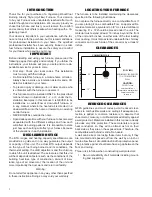
22”

12”

20”

15”

COMBUSTIBLE WALL

COMBUSTIBLE WALL

FLUE

(TOP VIEW)

MINIMUM CLEARANCES 

TO A COMBUSTIBLE 

WALL

CAUTION:

DO NOT store

combustible or

flammable materials or 

liquids near the

furnace.

Summary of Contents for VG7100

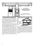
Page 1: ...talled a house fire may result For your safety follow these installation instructions Contact local building or fire officials about restrictions and installation requirements in your area This furnace must be installed by a qualified technician Keep these instructions for future reference Installation Operator s Manual SAVE THESE INSTRUCTIONS Certified for installations in the USA Safety Tested t...

Page 2: ...U output depends on the type of fuel being burned and its conditions the thermostat setting the draft adjustment and the chimney to which the unit is attached The actual area that this unit will heat depends on factors such as the conditions of the building heat loss type of construction amount of insu lation type of air movement the location of the unit and more importantly the duct work and retu...

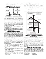
Page 3: ... certain it has a fire clay liner and that it is intact clean and recently inspected And remember masonry chimneys are far more prone to the formation of hazardous creosote 1 The furnace should be the only heating using the chim ney flue One furnace per flue outlet 2 A masonry chimney should have a tile or stainless steel liner 3 The masonry chimney should not have any missing mortar or loose bric...

Page 4: ...can be removed for cleaning 7 The connector pipe should not leave the heated por tion of the building to reach the chimney 8 The connector pipe should not pass from one story to the next before entering the chimney nor should it pass through any closed or enclosed space 9 The connector pipe and any elbows must be of 24 gauge or greater 10 The connector pipe should not be located near or in a walk ...

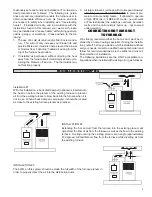
Page 5: ...nsulation melts and the motor simply burns up not covered under warranty CONNECTING HOT AIR DUCT TO FURNACE We strongly recommend that the hot air duct work be in stalled by a home heating specialist If doing the installa tion yourself before you decide which installation will best suit your needs consult a qualified heating technician and follow his recommendations as to the safest and most ef fi...

Page 6: ...decreased Without a return air system warm air will be drawn into your basement unnecessarily heating unused areas of the home In extreme cases if your base ment or utility room is fairly airtight the blowers on the furnace could depressurize the room and pull toxic flue gases from the furnace a gas water heater or gas fur nace The fumes could then be distributed throughout the house COMBUSTION AI...

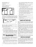
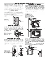
Page 7: ... brackets on the left side of the door frames as illustrated The slots in the brackets and latches are for door seal adjustment Make the proper adjustments then tighten the nuts The door s gasket should be snug against the door frame on the fur nace Feed Door Illustration Ash Door Illustration 1 Feed Door Latch 1 Ash Door Latch 4 1 4 20 x 3 4 Hex Bolt 4 1 4 20 Kep Nut BRACKET SHAKER GRATE HANDLE I...

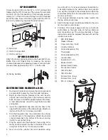
Page 8: ...lustration Attach the shorter conduit assembly to the bottom of the box securing it with the nut on the fitting 5 Plug the wires onto the snap disc see wiring sche matic and then attach the box to the back of the unit using four of the 10 x 1 2 screws provided 6 Next mount the junction box and insulation using two of the 10 x 1 2 screws provided Install the 5 x 5 insulation between the cabinet bac...

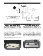
Page 9: ...K REPLACEMENT If baffle replacement is necessary slide the baffle out un til you can access the nuts thru the flue outlet Once the nuts have been removed slide the baffle off the rod and thru the opening in the firebrick You may have to remove one of the firebrick to make baffle removal easier There are 4 full brick and 1 half brick in the top of the furnace Install the brick by inserting one end ...

Page 10: ... an affected wood heat er Burning these materials may result in release of toxic fumes or render the heater ineffective and cause smoke Dead wood lying on the forest floor should be considered wet and requires full seasoning time Standing dead wood can usually be considered to be about 2 3 seasoned Split ting and stacking wood before it is stored accelerates dry ing time Storing wood on an elevate...

Page 11: ... combustible materials pending final disposal If the ashes are disposed of by burial in soil or otherwise locally dispersed they should be retained in the closed container until all coals have thoroughly cooled 3 With your poker push hot burning embers to the rear of the unit and add fresh coal in front NEVER load over height of firebrick This can result in damage to your furnace and home 4 Close ...

Page 12: ...wed 1 Any air filter should be removed 2 Observe the furnace operation closely and often till power is restored Do not burn garbage plastics gasoline drain oil or other flammable liquids Plastics when burned form hydrofluoric and hydrochloric acids which will damage and destroy your furnace pipe and chimney The burn ing of trash or oil can result in an extremely hot fire and is sometimes a cause o...

Page 13: ...s when exposed to elevated concentrations for extended periods of time While the modern combustion systems in heaters drastically reduce the amount of CO emitted out the chim ney exposure to the gases in closed or confined areas can be dangerous Make sure you stove gaskets and chimney joints are in good working order and sealing properly to ensure unintended exposure It is recommended that you use...

Page 14: ... cap is not too close to the top of the chimney D Check chimney draft make sure chimney flue pipe is clean and chimney is of adequate height E Make sure you re not suffocating the fire with excessive amounts of unburned wood F Slide baffle should be pulled out prior to load door opening 4 Problem Distribution blower vibrating Solution A Tighten blower wheel to motor shaft B Check for bad fan beari...

Page 15: ...enter of the firebox The first flames will be long and generally orange or yellow and produce quite a bit of smoke As the gases burn off the flames become shorter change color and produce less smoke Once the fire is WELL ESTABLISHED add coal to the cen ter of the firebox forming the cone Burning in this fashion allows heat to drive off the volatile gases and turbulence created increases the burn e...

Page 16: ... not necessary to shake down the ashes each time you refuel the furnace Experience will be your best teacher BANKING THE FIRE For extended operation such as overnight the fire will need to be banked To do so heap coal up along the sides and back of the firebox so that the fire gradually burns it over a longer period of time The intensity of the fire will also be reduced without letting it go out F...

Page 17: ...17 PARTS DIAGRAM 11 12 13 16 15 17 14 7 10 5 2 3 6 30 29 4 3 2 1 35 3 8 9 24 26 25 27 17 16 3 19 18 20 28 34 21 22 32 33 23 31 ...

Page 18: ... Gasket Flue Collar 88032 1 22 Flue Collar 40246 1 23 Flue Collar Ring 22761 1 24 Smoke Curtain 23800 1 25 Smoke Door Clip 23787 2 26 Carriage Bolt 1 4 20 x 1 1 4 Long 83445 2 27 Kep Nut 1 4 20 83250 2 28 Cabinet Side Left 69452 1 29 Cabinet Side Right 69453 1 30 Blank Receptacle Snap In 891127 1 31 Cabinet Back 25624 1 32 Insulation Panel C98871 1 N S Insulation Retainer 83884 12 33 Cabinet Top 6...

Page 19: ...r for your home Vogelzang offers the model UFB908 as an option and can be purchased from your local dealer The UFB908 utilizes a standard 16 x 20 filter that can be purchased from your local dealer or any hardware duct work supply store When installing a UFB908 follow the installation instructions supplied with the kit 6 7 8 USSC offers a forced induced draft blower kit as an op tion to upgrade yo...

Page 20: ...l and re attach to the furnace enclosure 7 The installation is now ready to be plumbed to your existing hot water system Choose one of the three methods described in the Hot Water Coil instructions Have a qualified plumber connect your domestic hot wa ter pipe to the coil with the appropriate fittings In the unlikely event that your furnace overfires a con dition evidenced by elbows stove pipes an...

Page 21: ...NOTES ...

Page 22: ...NOTES ...

Page 23: ...NOTES ...

Page 24: ...ual in a safe place for future reference When placing an order or for warranty claims please provide the following information found on the Certification Plate located below the ash door PART NUMBER PART DESCRIPTION MODEL NUMBER VG7100 SERIAL NUMBER______________ United States Stove Company 227 Industrial Park Road P O Box 151 South Pittsburg TN 37380 800 750 2723 ...

Reviews: