Installation & Start-up – HES Series
33
Troubleshooting.
The HES Series (“S” for
Smart
) is equipped with a PLC (programmable logic
controller) that controls all aspects of the operation. One of the functions of the PLC is to shut down
the machine when a problem arises and send a signal to the fault indicator light located on the far-left
side of the electrical panel. The red light is visible through the opening in the front casing and will
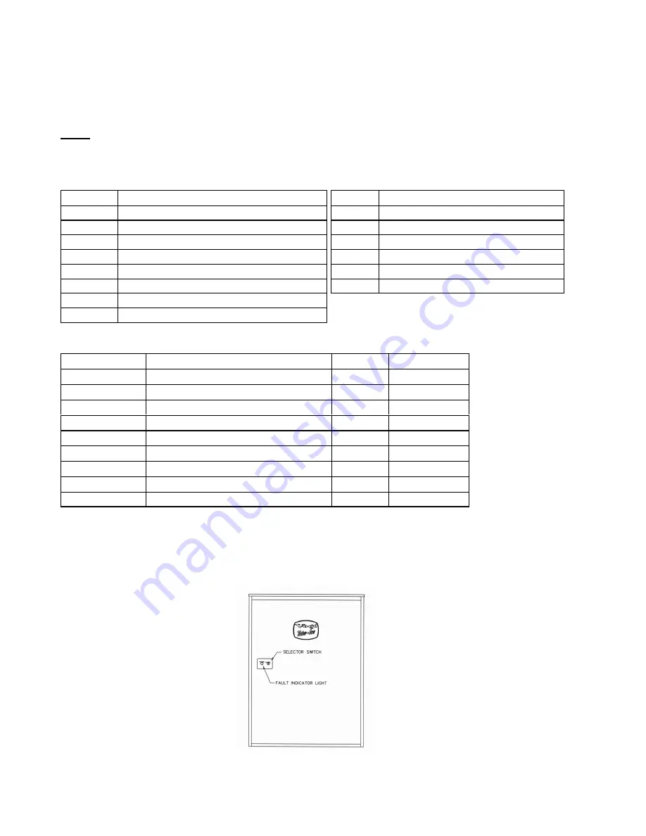
blink when a problem has caused the machine to shut down (See FIGURE-21).
Note:
The Fault Light will flash the designated number of times ONLY if the fault is a not a auto
restart
fault or a auto-restart fault that has occurred three consecutive times. For your reference,
TABLE-7 contains a list of the PLC Inputs, Outputs, and fault codes.
PLC Inputs
PLC Outputs
#
Description
#
Description
0
Cylinder Ice Indicator
0
Machine Fault Indicator Light
1
Crushed Ice Indicator
1
"A" valve
2
Freezer Pressure Switch
2
Compressor
3
Start / Manual Harvest
3
Reversing Relay
4
Clean Switch
4
Water Pump
5
Pump / Cutter Overload
(“off” when tripped)
5
Cutter / "D" valve / Suction Stop
6
High / Low Pressure safety
(“off” when tripped)
7
N/A
Machine Faults
#
Description
Restart
Off Delay
1
High / Low Press – Freeze
No
N/A
2
High / Low Press – Harvest
No
N/A
3
High / Low Press - Partial Pumpdown
No
N/A
4
High / Low Press - Total Pumpdown
No
N/A
5
Short Cycle
Yes
2 hrs
6
Long Cycle
No
N/A
7
Pump Motor Overload
Yes
30 min
8
Cutter Motor Overload
Yes
30 min
N/A
Power Failure
Yes
2 hrs
Note:
The machine may be off on a fault and not flashing an error code if the fault is an auto-
restart fault and it is not the third consecutive occurrence of this fault.
TABLE – 7
PLC Inputs, Outputs, and Fault Codes
FIGURE - 21
Fault Indicator / Selector Switch Location
Summary of Contents for HE S Series
Page 2: ...Installation Start up HES Series 2 Blank Page ...
Page 12: ...Installation Start up HES Series 12 FIGURE 8 Typical Space Diagram ...
Page 26: ...Installation Start up HES Series 26 FIGURE 16 Piping Schematic Air Cooled ...
Page 27: ...Installation Start up HES Series 27 FIGURE 17 Piping Schematic Water Cooled ...


