P24AL & P34AL Service Manual
OPTIONS AND ACCESSORIES
12/2016
10-2
The PLC/Interface adds features such as selectable “Automatic Restart” after a power failure, choice
of timed or pressure switch controlled freeze cycles and Freezer “Pumpdown”. For package units,
the machine will automatically “Pumpdown” before cycling off. The PLC/Interface provides the
following programmable functions:
Cutter delay (amount of time at start of harvest before cutter comes on).
Conveyor control contacts (delay at start of harvest before conveyor comes on and run time).
Automatic Restart after a Power Failure (enable/disable)
Auto-restart time (delay time before restarting – recommended 2 hours for package
machines)
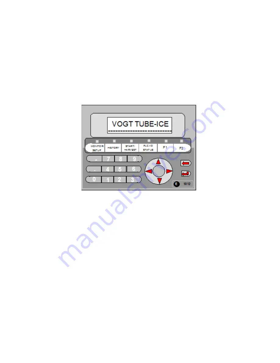
Figure 10-1
Mitsubishi E1012 Operator Interface
The PLC provides a MACHINE FAULT indication with an alarm relay. The PLC will log when the
fault occurred (time and date) and where in the cycle the machine was when the fault occurred. It
will store the last 5 faults in history, which can be accessed by pressing the HISTORY button on the
interface until the FAULT HISTORY title appears. Press the down arrow on the pad to scroll down t
through the information. Machine faults are listed below:
Compressor high discharge pressure
Compressor low suction pressure
Compressor oil pressure
Compressor motor fault
Cutter motor overload
Water pump motor overload
Long cycle – a freeze cycle lasting more than 60 minutes
Short cycle – 3 consecutive freeze cycles that are 5 minutes or less in duration
Power failure / Power return
Summary of Contents for P-24AL
Page 1: ...12 2016 P 24AL P 34AL TUBE ICE MACHINE Service Manual 5000 ...
Page 10: ...P24AL P34AL Service Manual TABLE OF CONTENTS 12 2016 vi ...
Page 15: ...P24AL P34AL Service Manual INTRODUCTION 12 2016 1 5 Figure 1 2 P24AL Right Side ...
Page 16: ...P24AL P34AL Service Manual INTRODUCTION 12 2016 1 6 Figure 1 3 P24AL Back Side ...
Page 17: ...P24AL P34AL Service Manual INTRODUCTION 12 2016 1 7 Figure 1 4 P24AL Left Side ...
Page 18: ...P24AL P34AL Service Manual INTRODUCTION 12 2016 1 8 Figure 1 5 P34AL Front Side Control Panel ...
Page 19: ...P24AL P34AL Service Manual INTRODUCTION 12 2016 1 9 Figure 1 6 P34AL Right Side ...
Page 20: ...P24AL P34AL Service Manual INTRODUCTION 12 2016 1 10 Figure 1 7 P34AL Back Side ...
Page 21: ...P24AL P34AL Service Manual INTRODUCTION 12 2016 1 11 Figure 1 8 P34AL Left Side ...
Page 22: ...P24AL P34AL Service Manual INTRODUCTION 12 2016 1 12 ...
Page 62: ...P24AL P34AL Service Manual START UP OPERATION 12 2016 5 8 ...
Page 84: ...P24A P34A Service Manual TROUBLESHOOTING 12 2016 8 12 ...
Page 110: ...P24AL P34AL Service Manual SERVICING OPERATIONS 12 2016 9 26 ...
Page 126: ...P24AL P34AL Service Manual TABLES CHARTS 12 16 16 11 8 ...
Page 130: ...P24AL P34AL Service Manual INDEX 12 2016 12 4 ...
Page 131: ...Appendix A ...
Page 134: ......
Page 136: ...i ...
Page 137: ...ii ...
Page 138: ...1 ...
Page 139: ...2 ...
Page 140: ...3 ...
Page 141: ...4 ...
Page 142: ...5 ...
Page 143: ...6 ...
Page 144: ...7 ...
Page 145: ...8 ...
Page 146: ...9 ...
Page 147: ...10 ...
Page 148: ...11 ...


