P24AL & P34AL Service Manual
TABLES & CHARTS
12/16/16
11-2
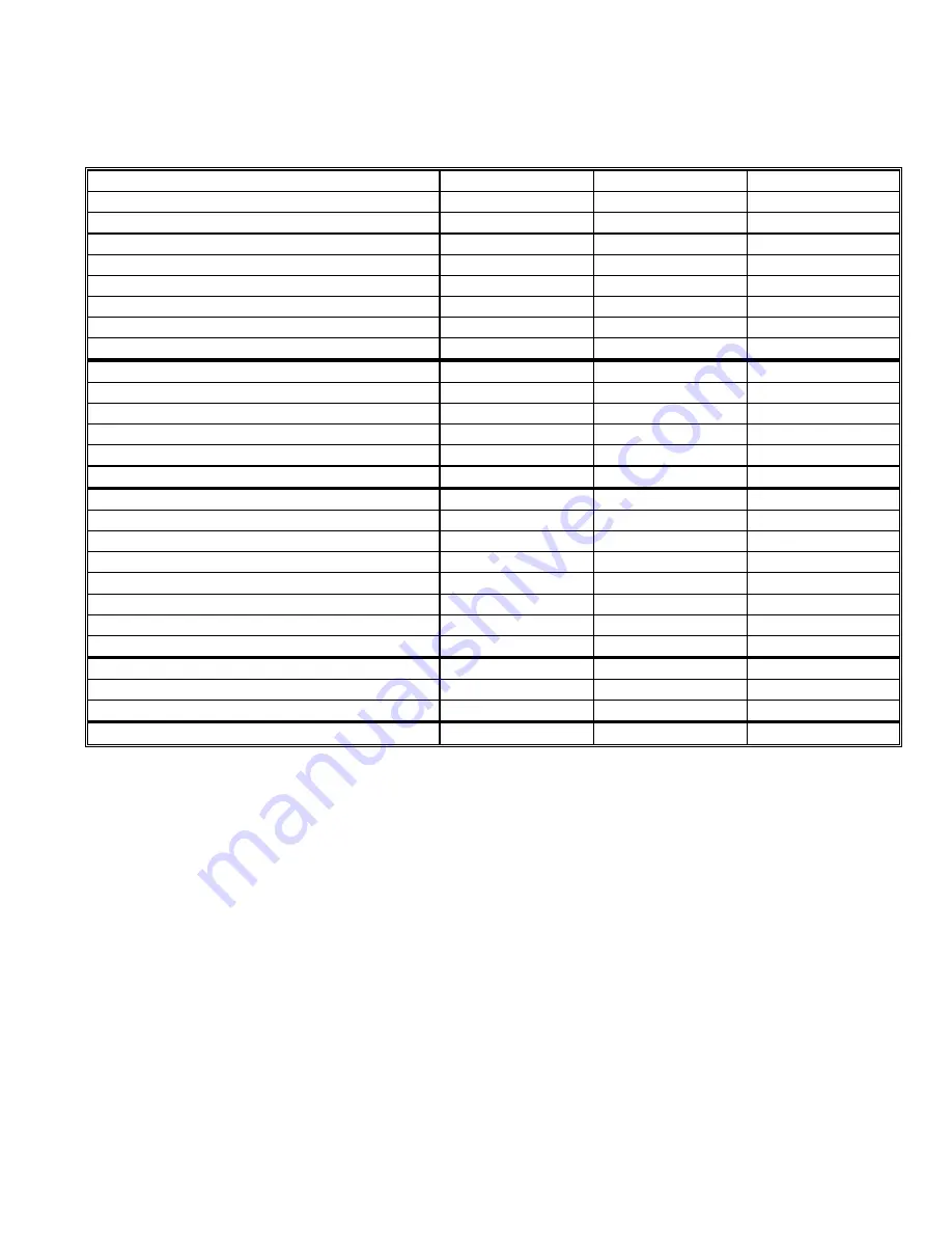
P34AL Specifications, 400/460 Volt-3 Phase- 50/60Hz
Tube Size
Inches
(cm)
1
(2.54)
1 1/4
(3.17)
1 1/2
(3.18)
Nominal Capacity
(1)
Tons/day
(M Tons/day)
39.2 (35.6)
40.7 (37.0)
31.0 (28.2)
Overall Dimensions (LxWxH)
Feet
(meters)
7x7x14.5 (2.1x2.1x4.4)
7x7x16 (2.1x2.1x4.8)
7x7x16 (2.1x2.1x4.8)
Shipping Weight
lbs
(Kg)
9,400 (4,260)
10,000 (4,530)
9,600 (4,350)
Operating Weight
lbs
(Kg)
10,450 (4,740)
11,400 (5,170)
11,200 (5,080)
Refrigerant Charge (R-717)
(2)
lbs
(Kg)
950 (431.0)
950 (431.0)
950 (431.0)
Total FLA
(3)
17.0
9.1
9.1
Maximum Fuse
30
15
15
Minimum Ampacity
17.5
7.6
7.6
System Requirements
- Dedicated Compressor
(4)
Tons
(KW)
87.9 (309)
81.9 (288)
58.6 (206)
- Average Refrigeration
(4)
Tons
(KW)
71.1 (250)
70.9 (249)
52.8 (186)
- Peak Refrigeration
(4)
Tons
(KW)
126.6 (445)
131.8 (463)
118.8 (418)
-Makeup
(5)
gpm
(m
3
/ Hr)
8.1 (1.8)
8.9 (2.0)
8.0 (1.8)
- Blow down per harvest (min)
Gallons
(L)
50 (189)
50 (189)
50 (189)
Connection Sizes
-Makeup water
FPT
1”
1”
1”
-Tank drain
FPT
2”
2”
2”
-Flush water
FPT
3/4”
3/4”
3/4”
-Tank overflow
FPT
3”
3”
3”
-Suction
Flanged
4”
4”
4”
-Liquid feed
FPT/Socket
1”
1”
1”
-Thaw gas
Flanged
2”
2”
2”
Compressor -HP-KW-FLA
Dedicated
125 - 93.2 - 156
125 - 93.2 - 156
125 - 93.2 - 156
Water Pump - HP-KW-FLA
10 - 7.4 - 12.0
3 - 2.2 - 4.1
3 - 2.2 - 4.1
Cutter Motor - HP-KW-FLA
2 - 1.5 - 3.2
2 - 1.5 - 3.2
2 - 1.5 - 3.2
THR
Btu/hr
(kW)
1,850,000 (542.0)
1,724,000 (505.2)
1,234,000 (362.0)
(1) Nominal capacity is based on 70°F makeup water, 16
F suction temperature, 100°F condensing temperature, 70°F ambient, and 25% blow down.
(2) For evaporator only. Dedicated system charge is 1,000 lbs., (454Kgs).
(3) FLA for 460 volt models is approximately 1/2 that of 230 volt models. Total FLA does not include cooling tower or auxiliary equipment.
(4) Compressor Requirements is based on 16
F suction temperature, 100°F condensing temperature, 70°F ambient, and 25% blow down.
(5) Makeup water is maximum value and includes 25% blow down each cycle.
Vogt reserves the right to change designs and specifications without notice.
Table 11-2
Summary of Contents for P-24AL
Page 1: ...12 2016 P 24AL P 34AL TUBE ICE MACHINE Service Manual 5000 ...
Page 10: ...P24AL P34AL Service Manual TABLE OF CONTENTS 12 2016 vi ...
Page 15: ...P24AL P34AL Service Manual INTRODUCTION 12 2016 1 5 Figure 1 2 P24AL Right Side ...
Page 16: ...P24AL P34AL Service Manual INTRODUCTION 12 2016 1 6 Figure 1 3 P24AL Back Side ...
Page 17: ...P24AL P34AL Service Manual INTRODUCTION 12 2016 1 7 Figure 1 4 P24AL Left Side ...
Page 18: ...P24AL P34AL Service Manual INTRODUCTION 12 2016 1 8 Figure 1 5 P34AL Front Side Control Panel ...
Page 19: ...P24AL P34AL Service Manual INTRODUCTION 12 2016 1 9 Figure 1 6 P34AL Right Side ...
Page 20: ...P24AL P34AL Service Manual INTRODUCTION 12 2016 1 10 Figure 1 7 P34AL Back Side ...
Page 21: ...P24AL P34AL Service Manual INTRODUCTION 12 2016 1 11 Figure 1 8 P34AL Left Side ...
Page 22: ...P24AL P34AL Service Manual INTRODUCTION 12 2016 1 12 ...
Page 62: ...P24AL P34AL Service Manual START UP OPERATION 12 2016 5 8 ...
Page 84: ...P24A P34A Service Manual TROUBLESHOOTING 12 2016 8 12 ...
Page 110: ...P24AL P34AL Service Manual SERVICING OPERATIONS 12 2016 9 26 ...
Page 126: ...P24AL P34AL Service Manual TABLES CHARTS 12 16 16 11 8 ...
Page 130: ...P24AL P34AL Service Manual INDEX 12 2016 12 4 ...
Page 131: ...Appendix A ...
Page 134: ......
Page 136: ...i ...
Page 137: ...ii ...
Page 138: ...1 ...
Page 139: ...2 ...
Page 140: ...3 ...
Page 141: ...4 ...
Page 142: ...5 ...
Page 143: ...6 ...
Page 144: ...7 ...
Page 145: ...8 ...
Page 146: ...9 ...
Page 147: ...10 ...
Page 148: ...11 ...


