P34AL-15 & P34ALOF-15 Service Manual
Options and Accessories
9/22/05
10-11
CHANGING THE SETUP VALUES
Several operating parameters of the machine can be modified. The set up screen must be accessed to
make any modifications. The set up screen can be accessed by pressing the “C” button on the
operator interface when the machine is in the freeze, harvest, pumpdown, clean or standby mode.
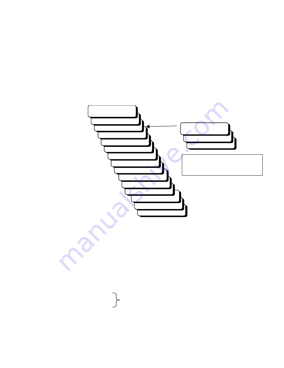
When on the setup screen the interface will display the information shown below. The arrow
buttons can be used to scroll through the lines of the screen.
SETUP SCREEN
C=MORE SETUP
B=MONITOR
CALC FRZ: ##.## M
SELCT SUC TMP: # F
AVG WTR TMP: ## F
RT WTR TMP: ## F
FRZ TIMER ##:##
A=TIMER OR TEMP
FRZ TIME: TEMP
CNVYR DLAY #### S
CNVYR RUN #### S
BLOWDOWN ### S
CUTTR DLAY ## S
HARVEST ### S
SETUP SCREEN
AUTOSTRT ### M
CNVYR DLAY: #### S
CNVYR RUN: #### S
SUCT DLAY: ##.# S
BLOWDOWN: #### S
Note: SUCT DLAY time
(delay opening of main suction valve)
used on cutterless machines
To change the value of a variable, scroll to that line, press the “SET” button on the interface, enter
the new value using the numeric key pad and press “ENTER” to accept the new value.
Note: When entering Freeze Time, press “SET” to enter minutes - press “SET” two times to enter
seconds.
The variables that can be changed from this screen are:
Auto-restart (autostrt) time: 5 to 180 minutes
Harvest time: 60 to 300 seconds
Cutter delay: 0 to 30 seconds
Suction delay: 0 to 180 seconds
Cutter or Suction valve delay
Blowdown time: 0 to 300 sec
Conveyor run time: 0 to 1200 seconds
Conveyor delay time: 0 to 300 seconds
Freeze Time: 0 to 35:59 minutes
Select Suction Temp: 1, 2 or 3
Summary of Contents for P-34AL-15
Page 1: ...P 34AL 15 P34ALOF 15 TUBE ICE MACHINE Service Manual 5000 9 22 05 ...
Page 2: ......
Page 5: ...9 22 05 ...
Page 8: ......
Page 14: ...P34AL 15 P34ALOF 15 Service Manual TABLE OF CONTENTS vi ...
Page 19: ...P34AL 15 P34ALOF 15 Service Manual INTRODUCTION 9 22 05 1 5 FIGURE 1 2 P34AL 15 Right Side ...
Page 20: ...P34AL 15 P34ALOF 15 Service Manual INTRODUCTION 9 22 05 1 6 FIGURE 1 3 P34AL 15 Left Side ...
Page 22: ...P34AL 15 P34ALOF 15 Service Manual INTRODUCTION 9 22 05 1 8 FIGURE 1 5 P34ALOF 15 Right Side ...
Page 23: ...P34AL 15 P34ALOF 15 Service Manual INTRODUCTION 9 22 05 1 9 FIGURE 1 6 P34ALOF 15 Left Side ...
Page 24: ...P34AL 15 P34ALOF 15 Service Manual INTRODUCTION 9 22 05 1 10 ...
Page 50: ...P34AL 15 P34ALOF 15 Service Manual INSTALLING YOUR TUBE ICE MACHINE 9 22 05 3 24 ...
Page 62: ...P34AL 15 P34ALOF 15 Service Manual START UP OPERATION 9 22 05 5 8 ...
Page 88: ...P34AL 15 P34ALOF 15 Service Manual TROUBLESHOOTING 9 22 05 8 13 ...
Page 130: ...P34AL 15 P34ALOF 15 Service Manual Options and Accessories 9 22 05 10 16 ...
Page 131: ...P34AL 15 P34ALOF 15 Service Manual TABLES CHARTS 9 22 05 11 1 11 Tables Charts ...
Page 138: ...Appendix A ...
Page 141: ......
Page 143: ...i ...
Page 144: ...ii ...
Page 145: ...1 ...
Page 146: ...2 ...
Page 147: ...3 ...
Page 148: ...4 ...
Page 149: ...5 ...
Page 150: ...6 ...
Page 151: ...7 ...
Page 152: ...8 ...
Page 153: ...9 ...
Page 154: ...10 ...
Page 155: ...1 ...
Page 159: ...P24AL P34AL Service Manual INDEX 9 22 05 12 4 ...


