P24AL & P34AL Service Manual
INDEX
9/22/05
12-1
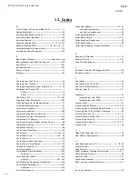
12. Index
A
A Brief History Of Henry Vogt Machine Co. ---------------- 1-1
Adding Refrigerant --------------------------------------------------- 5-6
Ammonia Specification by Grade -------------------------------- 5-2
Ammonia (amount required)--------------------------------------- 5-2
Ammonia Removal--------------------------------------------------9-19
Assembly Drawing P24AL ---------------------- 1-4, 1-5, 1-6, 107
Assembly Drawing P34AL ------------------- 1-8, 1-9, 1-10, 1-11
Automatic blowdown (Harvest Cycle) --------------------------- 9-1
Auxiliary Controls or Equipment ---------------------------------3-18
B
Basic Product Warranty ------------------------- inside back cover
Bearing Bracket and Cutter Disc Removal -------------------9-10
Belt Tension ----------------------------------------------------------9-27
Belt Replacement ---------------------------------------------------9-27
Bin Level Control ----------------------------------------------------- 6-1
Blowdown -------------------------------------------------------------- 9-1
C
Charging From Tank Truck ---------------------------------------- 5-3
Charging From Cylinders------------------------------------------- 5-3
Charging Refrigeration System (Precautions) --------- 1-3, 5-2
Charging Valve-Freezer (28) -------------------------------------------
P24AL----------------------------------------------------------- 1-4
P34AL----------------------------------------------------------- 1-8
Check Valve (101) ------------------------------------------ 1-11, 9-25
Circulating Water Pump Motor-----------------------------------9-23
Cleaning Procedure (Ice Making Section) --------------------- 7-3
Cleaning Ice Making Section -------------------------------------- 9-1
Compressor ( Optional ) -------------------------------------------- 7-6
Compressor Inspection --------------------------------------------9-26
Compressor Maintenance (Optional )--------------------------- 7-7
Compressor Loosing Oil Excessively --------------------------8-10
Compressor Oil Changing ----------------------------------------9-24
Compressor Running Unloaded During Freeze -------------- 8-9
Compressor Servicing ---------------------------------------------9-26
Condenser Cleaning------------------------------------------------- 9-6
Control Circuit Protection------------------------------------------- 9-5
Control Panel ---------------------------------------------- 5-5, 6-2, 6-3
Control Panel Parts -------------------------------------------6-2 , 6-3
Cooling Tower--------------------------------------------------------3-12
Cooling Tower/ Evap Condenser--------------------------------- 7-5
Cooling Tower Piping Diagram ----------------------- 3-14, 13-15
Crushed Ice Production--------------------------------------------10-2
Current Unbalance --------------------------------------------------3-17
Cutter Adapter Plate Installation --------------------------------9-18
adjustment ----------------------------------------------------9-18
Cutter Assembly (P24AL) ---------------------------------------- 9-14
parts list------------------------------------------------ 9-15, 9-16
Cutter Assembly Removal and Installation -------------------9-10
Cutter Blade Replacement----------------------------------------9-17
adjustment ----------------------------------------------------9-18
Cutter Disc Removal -----------------------------------------------9-10
Cutter Gear Reducer ------------------------------------------ 7-7, 9-7
drive gear replacement ------------------------------------- 9-7
gear reducer replacement --------------------------------- 9-8
Cutter Height Adjustment------------------------------------------- 9-3
Cutter Motor Starters ---------------------------------------------10-13
Cutter Ring Gear Replacement ----------------------------------- 9-7
Cutter Parts Weights ------------------------------------------------ 9-9
Cutter Shaft & Bearing Removal/Installation ---------------- 9-11
D
Description Of Machine --------------------------------------------- 2-1
Draining Oil Trap--------------------------------------------------- 9-21
Drive Gear Replacement ------------------------------------------- 9-7
E
Electrical Schematic, All Voltages 50-60 Hz. ----------------- 6-4
Electrical Controls ---------------------------------------------------- 6-1
F
Float Switch ------------------------------------------------------------ 9-1
Float Switch Stop Valve (10A) ------------------------------------ 1-9
Float Valve (Make-Up Water) ------------------------------------- 9-1
Flushing Water In--------------------------------------------------- 3-11
Foundation ------------------------------------------------------------- 3-1
foundation layout for P24AL -------------------------------- 3-4
foundation layout for P34AL -------------------------------- 3-7
Freeze Period --------------------------------------------------------- 4-1
Freeze Protection Diagram -------------------------------3-15, 3-16
Freeze-Up Due To Extended Freeze Period ------------------ 8-4
Freeze-Up Due To Ice Failing To Discharge ------------------ 8-5
Freezer Drain Valve (61) ---------------------------------- 1-6, 1-11
Freezer Pressure Switch (2PS)----------------------------------- 9-4
Freezer Purge Valve (76) ---------------------------------- 1-7, 1-10
Freezer Safety Valves (51) -------------------------- 1-6, 1-9, 3-13
Freezer Timer -------------------------------------------------------- 9-2
G
Gage Glass Stop Valve (31)--------------------------------------- 1-6
Gear Reducer Replacement--------------------------------------- 9-8
H
Hand Expansion Valve (17)--------------------------- 1-4, 1-8, 9-2
Harvest Period -------------------------------------------------------- 4-2
Head Pressure -------------------------------------------------------- 8-8
High Compressor Discharge Temperature ------------------ 8-11
High Discharge Pressure------------------------------------------- 8-8
Heat Rejection------------------------------------------------------- 3-13
High Suction Pressure ---------------------------------------------- 8-9
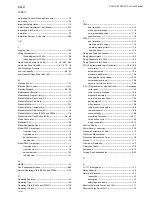
How Your Tube-Ice Machine Works----------------------------- 4-1
I
Ice Lb./Kg Harvest--------------------------------------------------- 2-2
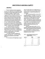
Summary of Contents for P-34AL-15
Page 1: ...P 34AL 15 P34ALOF 15 TUBE ICE MACHINE Service Manual 5000 9 22 05 ...
Page 2: ......
Page 5: ...9 22 05 ...
Page 8: ......
Page 14: ...P34AL 15 P34ALOF 15 Service Manual TABLE OF CONTENTS vi ...
Page 19: ...P34AL 15 P34ALOF 15 Service Manual INTRODUCTION 9 22 05 1 5 FIGURE 1 2 P34AL 15 Right Side ...
Page 20: ...P34AL 15 P34ALOF 15 Service Manual INTRODUCTION 9 22 05 1 6 FIGURE 1 3 P34AL 15 Left Side ...
Page 22: ...P34AL 15 P34ALOF 15 Service Manual INTRODUCTION 9 22 05 1 8 FIGURE 1 5 P34ALOF 15 Right Side ...
Page 23: ...P34AL 15 P34ALOF 15 Service Manual INTRODUCTION 9 22 05 1 9 FIGURE 1 6 P34ALOF 15 Left Side ...
Page 24: ...P34AL 15 P34ALOF 15 Service Manual INTRODUCTION 9 22 05 1 10 ...
Page 50: ...P34AL 15 P34ALOF 15 Service Manual INSTALLING YOUR TUBE ICE MACHINE 9 22 05 3 24 ...
Page 62: ...P34AL 15 P34ALOF 15 Service Manual START UP OPERATION 9 22 05 5 8 ...
Page 88: ...P34AL 15 P34ALOF 15 Service Manual TROUBLESHOOTING 9 22 05 8 13 ...
Page 130: ...P34AL 15 P34ALOF 15 Service Manual Options and Accessories 9 22 05 10 16 ...
Page 131: ...P34AL 15 P34ALOF 15 Service Manual TABLES CHARTS 9 22 05 11 1 11 Tables Charts ...
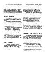
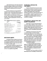
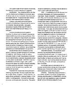
Page 138: ...Appendix A ...
Page 141: ......
Page 143: ...i ...
Page 144: ...ii ...
Page 145: ...1 ...
Page 146: ...2 ...
Page 147: ...3 ...
Page 148: ...4 ...
Page 149: ...5 ...
Page 150: ...6 ...
Page 151: ...7 ...
Page 152: ...8 ...
Page 153: ...9 ...
Page 154: ...10 ...
Page 155: ...1 ...
Page 159: ...P24AL P34AL Service Manual INDEX 9 22 05 12 4 ...


