P24AL & P34ALService Manual
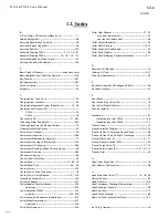
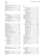
INDEX
9/22/05
12-3
Refrigerant, Adding -------------------------------------------------- 5-6
Refrigerant Leaks ---------------------------------------------------9-19
Refrigerant Charge--------------------------------------------------- 5-2
Refrigerant, Removal-----------------------------------------------9-18
Refrigeration System Review ------------------------------------- 5-1
Removing Excess Water from Ammonia----------------------9-21
Rotation Check-------------------------------------------------------3-17
S
Safety Notice ---------------------------------------------------------- 1-2
Safety Switches------------------------------------------------------- 6-1
Safety Symbols and What They Mean-------------------------- 1-2
Safety Tags And Labels -------------------------------------------- 2-2
Safety Valves --------------------------------------------------------3-13
--------------------------- see figures 1-6 through 1-11 for location
Servicing Operations ------------------------------------------------ 9-1
Shipping weight ------------------------------------------------------- 2-3
Soft Start Cutter Motor Starters-------------------------------- 10-13
initial torque adjustment --------------------------------- 10-13
start time adjustment------------------------------------- 10-13
wiring --------------------------------------------------------- 10-13
Solenoid Valves ------------------------------------------------------ 9-3
---------------------------- see figures 1-1 through 1-9 for location
Space Requirements ----------------------------------------------- 3-1
Space Diagram (P24AL) ------------------------------------- 3-2, 3-3
Space Diagram (P34AL) ------------------------------------- 3-5, 3-6
Spare Parts List (P24AL and P34AL) --------------------------11-6
Specifications for P24AL ------------------------------------2-3, 11-2
Specifications for P34AL ------------------------------------2-3, 11-3
Start Push Button (2PB) ------------------------------------- 5-5, 6-3
Start Time Adjustment (Soft Starter) ------------------------- 10-13
Start-Up ----------------------------------------------------------------- 5-5
Start-Up & Operation ------------------------------------------------ 5-1
Start-Up Checklist ---------------------------------------------------- 5-2
Storage (prior to installation and start-up) --------------------- 2-3
Stop Push Button (1PB) -------------------------------------- 5-5, 6-3
Suction Line Frosting to Compressor --------------------------8-12
Suction Regulating Valve -----------------------------------3-12, 5-7
T
Temperature-Pressure Chart-------------------------------------11-7
Thaw Gas Check Valve (101) -----------------------------1-7, 9-25
Thaw Gas Regulating Valve (18)----- 1-5, 1-9, 9-23, 9-24, 5-7
Thaw Gas Stop Valve (90)----------------------------------- 1-5, 1-9
Thawing Timer (2TR)------------------------------------------------ 9-5
Three Way Valve (52) ----------------------------------------1-6, 1-10
Troubleshooting------------------------------------------------------- 8-1
U
V
Valves ------------------------------------------------------------------9-22
Valves (location) ---------------------see figures 1-1 through 1-12
Voltage Unbalance -------------------------------------------------3-16
W
Warranty (Basic Product) ----------------------- inside back cover
Water Cooled Condenser Cleaning ----------------------------- 9-6
Water Distributors ---------------------------------------------------------
chart ------------------------------------------------------------- 7-3
cleaning procedure ------------------------------------------ 7-4
Water Flush Solenoid Valve (63) ------------------ 1-4, 1-9, 9-26
Water Tank----------------------------------------------7-4, 9-13, 9-15
Water Tank Drain Valve (39) -------------------------------- 1-4, 1-9
Water Tank and Cutter Parts Weights -------------------------- 9-9
Water Tank Assembly (P24AL) --------------------------------- 9-15
parts list------------------------------------------------------- 9-16
Water Tank Drain--------------------------------------------------- 3-11
Water Tank Installation ------------------------------------------- 9-13
Water Tank Overflow ---------------------------------------------- 3-11
Water Tank Removal ------------------------------------------------ 9-9
Wiring and Electrical Connections ----------------------------- 3-16
Wiring ( Soft Starter) ----------------------------------------------10-13
Wiring Schematic, All Voltages - 50/60 Hz -------------------- 6-4
X
Y, Z
Summary of Contents for P-34AL-15
Page 1: ...P 34AL 15 P34ALOF 15 TUBE ICE MACHINE Service Manual 5000 9 22 05 ...
Page 2: ......
Page 5: ...9 22 05 ...
Page 8: ......
Page 14: ...P34AL 15 P34ALOF 15 Service Manual TABLE OF CONTENTS vi ...
Page 19: ...P34AL 15 P34ALOF 15 Service Manual INTRODUCTION 9 22 05 1 5 FIGURE 1 2 P34AL 15 Right Side ...
Page 20: ...P34AL 15 P34ALOF 15 Service Manual INTRODUCTION 9 22 05 1 6 FIGURE 1 3 P34AL 15 Left Side ...
Page 22: ...P34AL 15 P34ALOF 15 Service Manual INTRODUCTION 9 22 05 1 8 FIGURE 1 5 P34ALOF 15 Right Side ...
Page 23: ...P34AL 15 P34ALOF 15 Service Manual INTRODUCTION 9 22 05 1 9 FIGURE 1 6 P34ALOF 15 Left Side ...
Page 24: ...P34AL 15 P34ALOF 15 Service Manual INTRODUCTION 9 22 05 1 10 ...
Page 50: ...P34AL 15 P34ALOF 15 Service Manual INSTALLING YOUR TUBE ICE MACHINE 9 22 05 3 24 ...
Page 62: ...P34AL 15 P34ALOF 15 Service Manual START UP OPERATION 9 22 05 5 8 ...
Page 88: ...P34AL 15 P34ALOF 15 Service Manual TROUBLESHOOTING 9 22 05 8 13 ...
Page 130: ...P34AL 15 P34ALOF 15 Service Manual Options and Accessories 9 22 05 10 16 ...
Page 131: ...P34AL 15 P34ALOF 15 Service Manual TABLES CHARTS 9 22 05 11 1 11 Tables Charts ...
Page 138: ...Appendix A ...
Page 141: ......
Page 143: ...i ...
Page 144: ...ii ...
Page 145: ...1 ...
Page 146: ...2 ...
Page 147: ...3 ...
Page 148: ...4 ...
Page 149: ...5 ...
Page 150: ...6 ...
Page 151: ...7 ...
Page 152: ...8 ...
Page 153: ...9 ...
Page 154: ...10 ...
Page 155: ...1 ...
Page 159: ...P24AL P34AL Service Manual INDEX 9 22 05 12 4 ...


