7-6
P34AL-15 & P34ALOF-15 Service Manual
MAINTENANCE
9/22/2005
! CAUTION !
Follow all lock-out and tag-out procedures before servicing any electrical equipment.
! CAUTION !
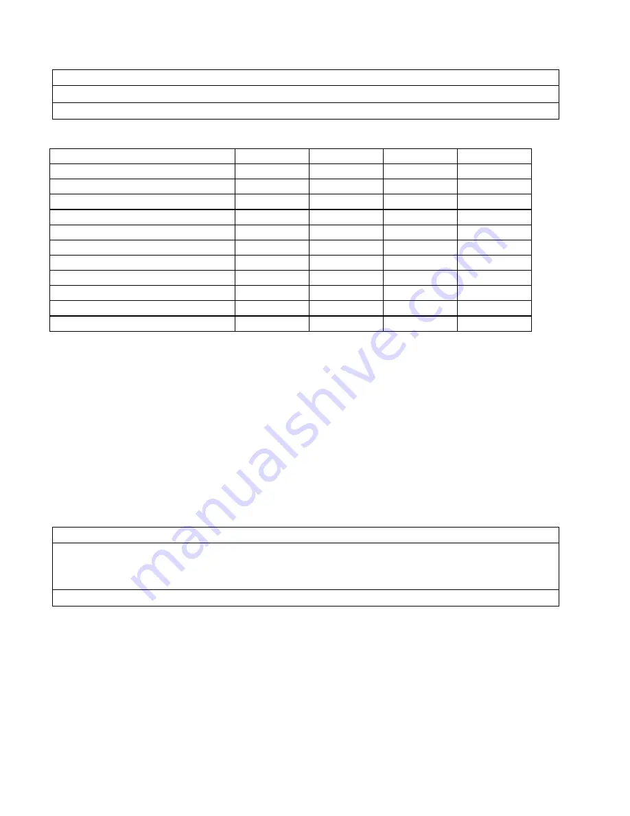
Service/Frequency Start-Up
Monthly Six
Months Shutdown
Clean debris from unit
X
X
X
Clean strainer and flush sump
X
X
X
Check fan and pump rotation
X
Clean spray nozzles
X
X
Check belt tension
X
X
Check for noise/vibration
X
X
Check/adjust make-up water valve
X
X
Check/adjust bleed rate
X
X
Check/lubricate
fan
bearings X X
Lubricate motor base adj. screw
X
X
X
Drain sump and piping
X
TABLE 7-3
Cooling Tower Maintenance Schedule
Compressor (optional).
This section is only a guide; please consult the compressor manual for
manufacturers recommended maintenance.
In starting and charging the unit, the oil sight glass should be continually checked to make sure an
adequate oil level is maintained. The oil level should be 1/4-3/4 of the sight glass. If the oil level
drops below 1/4 of the glass, add refrigeration oil as per the compressor manufacturer
recommendations. Never allow the oil level to be out of sight, above or below the sight glass when
the compressor is operating.
! CAUTION !
The crankcase heater should be energized for a minimum of
four hours and the oil temperature should be 100
°
-110
°
F
before attempting to start the compressor.
! CAUTION !
During operation, the specified net oil pressure should be maintained for proper lubrication and
operation of the cylinder unloader mechanism.
Mycom N&W Series net oil pressure: 17-28 psig
Vilter 450 Series net oil pressure: 35-50 psig
Summary of Contents for P-34AL-15
Page 1: ...P 34AL 15 P34ALOF 15 TUBE ICE MACHINE Service Manual 5000 9 22 05 ...
Page 2: ......
Page 5: ...9 22 05 ...
Page 8: ......
Page 14: ...P34AL 15 P34ALOF 15 Service Manual TABLE OF CONTENTS vi ...
Page 19: ...P34AL 15 P34ALOF 15 Service Manual INTRODUCTION 9 22 05 1 5 FIGURE 1 2 P34AL 15 Right Side ...
Page 20: ...P34AL 15 P34ALOF 15 Service Manual INTRODUCTION 9 22 05 1 6 FIGURE 1 3 P34AL 15 Left Side ...
Page 22: ...P34AL 15 P34ALOF 15 Service Manual INTRODUCTION 9 22 05 1 8 FIGURE 1 5 P34ALOF 15 Right Side ...
Page 23: ...P34AL 15 P34ALOF 15 Service Manual INTRODUCTION 9 22 05 1 9 FIGURE 1 6 P34ALOF 15 Left Side ...
Page 24: ...P34AL 15 P34ALOF 15 Service Manual INTRODUCTION 9 22 05 1 10 ...
Page 50: ...P34AL 15 P34ALOF 15 Service Manual INSTALLING YOUR TUBE ICE MACHINE 9 22 05 3 24 ...
Page 62: ...P34AL 15 P34ALOF 15 Service Manual START UP OPERATION 9 22 05 5 8 ...
Page 88: ...P34AL 15 P34ALOF 15 Service Manual TROUBLESHOOTING 9 22 05 8 13 ...
Page 130: ...P34AL 15 P34ALOF 15 Service Manual Options and Accessories 9 22 05 10 16 ...
Page 131: ...P34AL 15 P34ALOF 15 Service Manual TABLES CHARTS 9 22 05 11 1 11 Tables Charts ...
Page 138: ...Appendix A ...
Page 141: ......
Page 143: ...i ...
Page 144: ...ii ...
Page 145: ...1 ...
Page 146: ...2 ...
Page 147: ...3 ...
Page 148: ...4 ...
Page 149: ...5 ...
Page 150: ...6 ...
Page 151: ...7 ...
Page 152: ...8 ...
Page 153: ...9 ...
Page 154: ...10 ...
Page 155: ...1 ...
Page 159: ...P24AL P34AL Service Manual INDEX 9 22 05 12 4 ...


