10TA Service Manual
SERVICE OPERATIONS
4/28/14
9-2
Float switch assembly
Part No.
Switch assembly only
Part No.
Float Switch
(Part No.
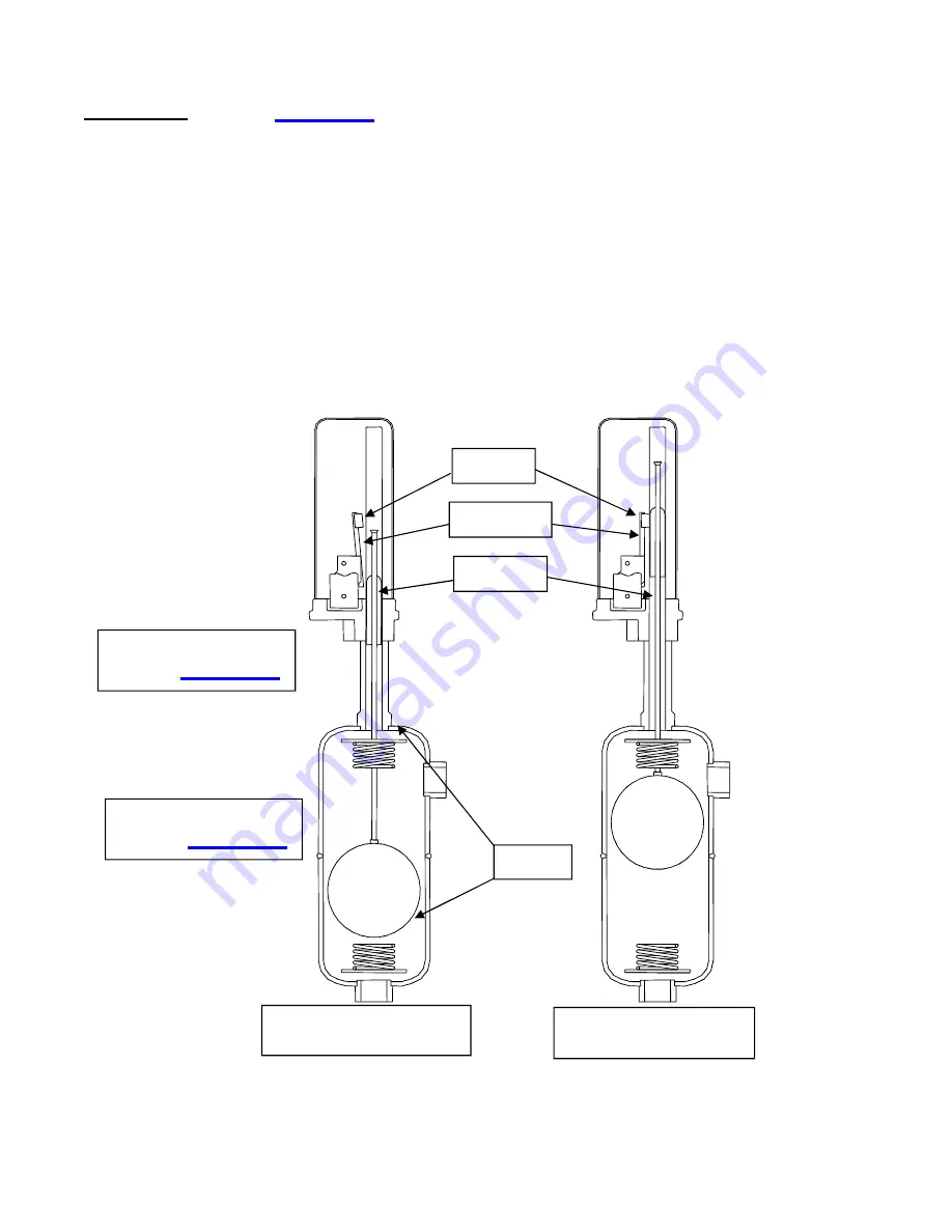
The float switch is installed on a header assembly that is
attached to the freezer shell. Valves are provided for isolation of the float switch assembly if
replacement or servicing is necessary. The float switch closes as the level of refrigerant in the
freezer rises and opens as the level falls.
The float switch is connected to the liquid feed solenoid valve (“A” valve) coil. This is the solenoid
valve directly before the hand expansion valve. Therefore when the refrigerant level in the freezer
drops, the float switch opens, thereby de-energizing the normally open liquid feed solenoid until
sufficient level has been reached to close the float switch. The float switch has a fixed 1/2”
differential.
The float switch is installed at the correct height at the factory and should not need to be adjusted.
The float switch is installed at the position that provides highest capacity. The correct height will
produce compressor superheat which climbs throughout the freeze cycle to a minimum of 30° F.
FIGURE 9-2
Hansen Refrigerant Float Switch
Float calling for refrigerant
Float satisfied – Not
calling for refrigerant
Attractor
Lever Arm
Magnet
Springs
Summary of Contents for P18FXT
Page 4: ...Vogt Tube Ice Machines Installation Service Manual and Parts Catalog 12A4171M08 10TA Model ...
Page 10: ...10TA Service Manual TABLE OF CONTENTS vi BLANK ...
Page 20: ...10TA Service Manual INTRODUCTION 4 14 14 1 10 BLANK ...
Page 40: ...10TA Service Manual INSTALLING YOUR TUBE ICE MACHINE 4 14 14 3 18 BLANK PAGE ...
Page 50: ...10TA Service Manual START UP AND OPERATION 4 14 14 5 6 BLANK ...
Page 60: ...10TA Service Manual ELECTRICAL CONTROLS 4 14 14 6 10 BLANK ...
Page 112: ...10 8 10TA Service Manual OPTIONS AND ACCESSORIES BLANK ...
Page 120: ...10TA Service Manual TABLES CHARTS 7 2 14 11 8 BLANK ...


