05TA Service Manual
SERVICE OPERATIONS
8/13/01
9-9
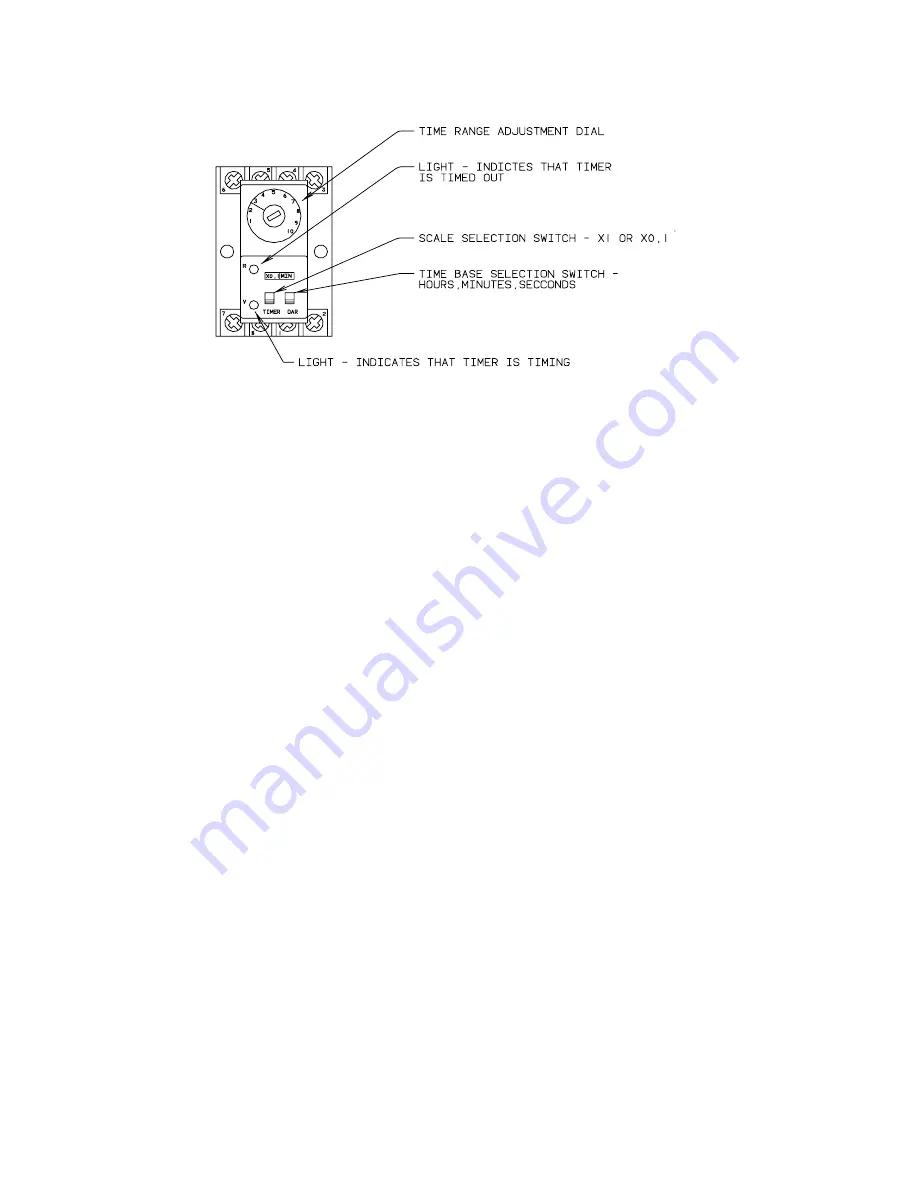
FIGURE 9-5
Thawing Timer
Thawing Timer.
The thawing timer governs the ice thawing period. It is located inside the control
panel (FIGURE 6-1). It is started by action of the freezer pressure switch (FPS) which energizes the
“CR” relay. This timer is set prior to shipment for approximately a two minute period.
Set the thawing period for at least 30 seconds longer than the time required to harvest the entire
discharge of ice. If it should be necessary to change the setting of the timer, turn the adjustment
screw clockwise to increase the time or counter-clockwise to decrease the time. Check thaw time
after each adjustment.
Control Circuit Protection.
The electrical control circuit of the machine is protected by two 2.5
amp fuses. If either of these fuses should open, the machine will immediately stop. Before replacing
a fuse, open the disconnect switch to machine and set the “On/Off” switch to the “off” position. If
the machine was off for an extended time the crankcase heater must be energized for a minimum of
two hours before restarting the machine. When ready to restart the machine, depress the “Start”
button. The machine will automatically return to a freeze cycle upon completion of the harvest cycle.
Condenser Cleaning.
See “Water Cooled Condensers”, “Maintenance”, Section 7.
Air-Cooled Condenser.
Visual inspection will indicate if dirt is accumulating and clogging the fin
face of the condenser. A vacuum cleaner, compressor air or a brush may be used to remove an
accumulator of dirt from the fin section of the condenser.
Cutter Gear Reducer.
The oil level for the gear reducer should be checked if there is evidence of a
leak. It should be level with the plugged opening in the side of the gear housing. Use Mobile 600W
cylinder oil or equal. Change oil once a year.
The motor bearings are prelubricated and require no further lubrication. For additional information,
refer to manufacturer’s instructions.
Summary of Contents for TUBE-ICE 05TA
Page 4: ...Vogt Tube Ice Machines Installation Service Manual and Parts Catalog 12A4171M06 05TA Model ...
Page 82: ...05TA Service Manual SERVICE OPERATIONS 8 13 01 9 18 FIGURE 9 10 Cutter Drive Parts ...
Page 95: ...05TA Service Manual OPTIONS AND ACCESSORIES 8 13 01 10 11 FIGURE 10 3 Control Panel Parts ...
Page 97: ...05TA Service Manual OPTIONS AND ACCESSORIES 8 13 01 10 13 FIGURE 10 4 Wiring Schematic ...
Page 103: ...05TA Service Manual TABLES CHARTS 8 14 01 11 1 11 Tables Charts ...


