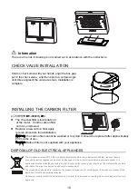
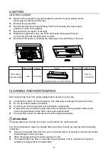
background image

LIGHTING


LIGHT REPLACEMENT 

Switch o

 the extractor hood and isolate the extractor hood by pulling out the

mains plug or switching o

 the fuse.

Remove the grease filter.

Remove the light by levering its fitting from the hood body (this may require

pressure or force to be applied).

Disconnect the connector of the light.

Replace the light with a new one of the same type,making sure that you

connect the light with the light cable correctly.

Reconnect the power by inserting the mains plug or by switching on the fuse.


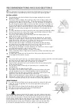
CLEANING AND MAINTENANCE

Disconnect range hood from power supply before cleaning or servicing.

Cleaning the surface of hood frequently. Use mild soap or detergent to clean the hood.

Do not use harsh alkalis or abrasives

.

Avoid the use of scouring powers or dishwasher compounds.

Grease filter may be washed using mild soap or detergent. (Heavy grease build-up may 

not be cleaned easily and the filter may require replacement).

Charcoal filter cannot be cleaned and must be replaced regularly.
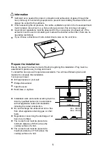

Information 

Cleaning water must not inter into motor, control switch etc. electrical parts.

It is recommendable to clean the metallic filter every three months by carrying out the following 

instruction:

Remove the metallic filter from the cooker hood and wash it in asolution of water and neutral 

liquid detergent, leaving to soak.

Rinse thoroughly with warm water and leave to dry.

The metallic filter may alter in color after several washes. This is notcause for customer 

complaint or replacement of metallic filter.
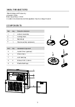
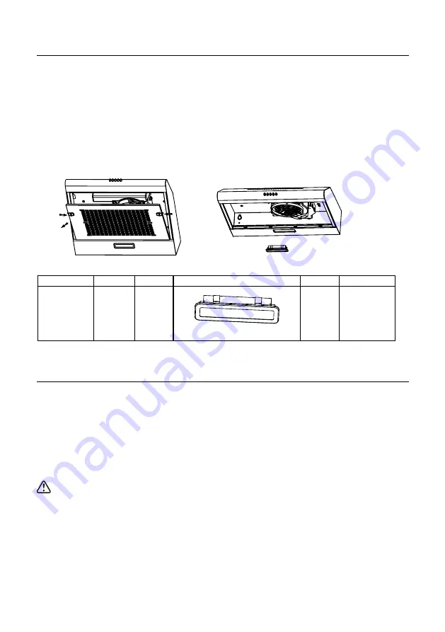

LED modules,

separete ballast

DSH-1.5-

S-33.2/120

Max power Voltage

Picture

Lamp Cap

ILCOS D code

1.5W

Square/Diameter:33.2mmx120mm

220-240V

9

Summary of Contents for 330171

Page 1: ...Rangehood 600mm SS 330171 INSTALLATION INSTRUCTIONS USER GUIDE To prevent the risk of accidents or damage to the appliance it is essential to read these instructions before it is installed and used for the first time ...

Page 2: ...stall the screws or fixing device in accordance with these instructions may result in electrical hazards For safety reason please use only the same size of fixing or mounting screw which are recommended in this instruction manual USE The cooker hood is only for home use not suitable for barbecue roast shop and other commercial purposes Never use the hood for purposes other than for which it has be...

Page 3: ...ly optional 2 6 7 1 2 3 4 Ref Qty Installation Components 5 1 Carbon Filter optional 6 1 Check Valve 7 1 Air Outlet Cap 8 4 Screws 5mm x 49mm 9 4 Plastic Wall Plugs Rated Voltage and Frequency 220 240V 50Hz Motor Input Power 125W In certain circumstances electrical appliance may be a danger hazard MAIN PARAMETERS 3 ...

Page 4: ...DIMENSIONS 650mm Min 500 140 Ф120 597 650mm Min unit mm Ø120 500 597 140 4 ...

Page 5: ...y are very easily damaged during installation if grazed or knocked by tools Please take care to protect the surfaces during installation Protect the cooktop surface below with cardboard or the like to prevent damage occurring whilst the wall canopy is being installed above The manufacturer shall not be liable for failure to observe all safety regulations in force for the correct and normal operati...

Page 6: ...as been turned off before beginning this installation Plug must be assembled in places easy to drag and insert To install this hood you will require two assistants You will need following tools and material to complete this installation Tools you will need Drill appropriate to your wall Phillips Screwdriver Tape Measure Hand Saw or Jig Saw Installation work and electrical wiring must be done by qua...

Page 7: ...unt on the wall drill two10mm diameter holes 538mm with the vent hole on the top of the cooker hood in the middle as below picture Make sure the hood is aligned directly over the hob Insert two plastics wall plugs supplied into the holes Insert two screws into the upper two plastic wall plugs and tighten them leaving 3mm protruding from the wall Mount the cooker hood onto the two screws and mark t...

Page 8: ...ess again to turn them off OFF MOTOR SWITCH Press on this switch to stop the motor operation SPEED SWITCH Press on this switch the motor runs at LOW speed SPEED SWITCH Press on this switch the motor runs at MEDIUM speed SPEED SWITCH Press on this switch the motor runs at HIGH speed 8 ...

Page 9: ...sives Avoid the use of scouring powers or dishwasher compounds Grease filter may be washed using mild soap or detergent Heavy grease build up may not be cleaned easily and the filter may require replacement Charcoal filter cannot be cleaned and must be replaced regularly Information Cleaning water must not inter into motor control switch etc electrical parts It is recommendable to clean the metall...

Page 10: ...they contain and reduce the impact on human health and the environment The crossed out wheeled bin symbol on the product reminds you of your obligation that when you dispose of the appliance it must be separately collected Consumers should contact their local authority or retailer for information concerning the correct disposal of their old appliance Information There is a fire risk if cleaning is ...

Page 11: ...eal with glue Leakage from the connection of U shaped section and cover Take U shaped section down and seal with soap or paint Vibration The blade if damaged can cause vibrating Replace the blade The motor is not tightly fastened Fasten the motor tightly The cooker hood is not tightly fixed Fixed the cooker hood tightly Insufficient suction The distance between the cooker hood and the cooker top i...

Page 12: ......

Reviews: