background image

Ikarray-8

Passive Plug&Play Line-Array

Manual

Summary of Contents for Ikarray-8

Page 1: ...Ikarray 8 Passive Plug Play Line Array Manual ...

Page 2: ... in the firm belief that details matter May we wish you a lot of pleasure with this product Muchas gracias por haber comprado un producto de Voice Acoustic Desdel año 2006 estamos desarrollando nuestros productos estando convencidos que son los detalles que cuentan Le s deseamos mucha alegría usando este producto Merci beaucoup d avoir acheté un produit Voice Acoustic Depuis 2006 nous développons ...

Page 3: ...ables 7 Operation 7 Working with Ikarray 8 Standard Configurations 8 Connection of 4 elements to HDSP 6 amplifier 9 Connection of 2 elements to HDSP 3 amplifier 10 Connection of 2 elements to Paveosub 118sp 11 Operation on tripod or spacer rod 12 Ikarray 8 in flight operation 12 Overview Accessories 13 Manufacturer s declaration Imprint 14 Contents ...

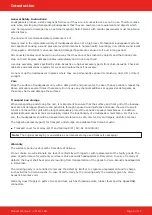
Page 4: ...aggressive detergents as these may harm and damage the surfaces Transport and storage When transporting and storing the unit it is important to ensure that the surface and front grill of the loudspe aker are not damaged Moisture can penetrate through exposed wood surfaces and cause the wood to swell A bent or broken front grill will no longer adequately protect the sensitive speaker membranes In a...

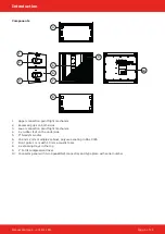
Page 5: ...ction point flight mechanics 4 4 x rubber feet on the underside 5 8 Neodym woofer 6 15 and 12 mm multiplex cabinet polyurea coating in RAL 9005 7 Front grille 1 mm with 10 mm acoustic foam 8 4 x stacking trays in the top 9 1 Ferrit compression driver 10 Connector panel with two SpeakON connectors and type plate with serial number 4 5 6 10 7 8 3 1 2 9 ...

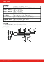
Page 6: ...100 x 15 or 100 x 5 depending on the housing version Powerhandling 500 W AES 1 000 W program 2 000 W peak at 4 Ω Sound pressure 15 Sound pressure 5 131 dB SPL AES 134 dB SPL program 137 dB SPL peak 133 dB SPL AES 136 dB SPL program 139 dB SPL peak Dimensions Weight 465 h x 513 w x 291 mm d 26 2 kg Finish Polyurea coating in RAL 9005 Connections The loudspeaker has a Neutrik NL4 SpeakON IN and OUT ...

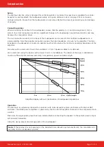
Page 7: ...e amplifier The total impedance of loudspeakers connected in parallel must not drop below the minimum operating impedance of the amplifier Voice Acoustic recommends to use the available 4 x 4 mm Speakon cables for mobile use We recommend wiring the basses with at least 4 mm in installations The cables of the tops in installations must be sufficiently dimensioned according to impedance power and ca...

Page 8: ...andard Configurations The HDSP amplifiers and self powered subwoofers contain presets for the following configurations Display name Coverage range Configurations IK8 15 100 x 15 15 IK8 5 15 100 x 20 5 15 IK8 5 5 5 15 100 x 30 5 5 5 15 IK8 5 5 15 15 100 x 40 5 5 15 15 ...

Page 9: ...ole cable coming from the amplifier is always first connected to the 5 element and then looped through to a 15 element Pin assignment upper Speakon socket Speakon 1 1 OUT CH3 800 W Speakon 2 2 OUT CH2 800 W Pin assignment lower Speakon socket Speakon 1 1 OUT CH2 800 W Speakon 2 2 OUT CH1 2 400 W Module 1 Module 2 15 15 5 5 Working with Ikarray 8 ...

Page 10: ...y via the upper Speakon socket the second element is looped through at the lower Speakon socket of the subwoofers Pin assignment upper Speakon socket Speakon 1 1 OUT CH3 800 W Speakon 2 2 OUT CH2 800 W Pin assignment lower Speakon socket Speakon 1 1 OUT CH2 800 W Speakon 2 2 OUT CH1 2 400 W Module 1 15 15 Working with Ikarray 8 ...

Page 11: ...require a Y adapter cable to connect the 800 W channels 1 1 of the two SpeakON connectors to a 4 pole Speakon cable LF 2 2 HF 1 1 Pin assignment left Speakon socket Speakon 1 1 OUT CH3 800 W Speakon 2 2 OUT CH2 800 W Pin assignment right Speakon socket Speakon 1 1 OUT CH2 800 W Speakon 2 2 OUT CH1 2 400 W Y Adapter 15 5 CH3 1 1 2 pole 1 1 2 2 4 pole 4 pole CH2 1 1 2 pole Working with Ikarray 8 ...

Page 12: ...il with ball locking pins 2 Fix threaded spindle with ball locking bolt B 3 Mount the connecting straps with ball lock pin C 4 Mount the holder for tripod distance rod on the mechanics 5 Place the loudspeaker on the mechanics and connect it with ball lock bolts Then connect the second speaker to the lower speaker at the connection points Ikarray 8 in flight operation max load four Ikarray 8 elemen...

Page 13: ...ort cover for Ikarray 8 15 and Ikarray 8 5 Art Nr 501801000 Heavy Duty Flightcase for up to 2 x Ikarray 8 15 or Ikarray 8 5 Art Nr 501803000 Self lock clamp for pipe 48 51mm 30mm wide max 250 kg Art Nr 999950731 Tripod transducer with M10 threaded connection Art Nr 999924528 Universal suspension arrangement for flight mechanics Art Nr 409992001 ...

Page 14: ...ations stipulating the continual improvement of product features For the safe operation of the unit this manual and all other required information must be available to all users at the time of assembly and disassembly of the unit and during opera tion Assemble or operate the unit only after reading and understan ding this manual and keeping it at hand at all times at the site We are happy to recei...

Reviews: