background image

Page 9

Processor

 Series

acoustics

Service

This  unit  has  very  sophisticated  circuitry  and  should  only  be  serviced  by  a  fully 

trained technician. 

                   To prevent electric shock, do not remove covers  
                                No user serviceable parts inside 
                         Refer servicing to a qualified technician

Worldwide Service

Service may be obtained from your local authorised service centre. To obtain service, 

simply present your sales receipt as proof of purchase along with the defective unit to 

an authorised service centre. They will handle the necessary paperwork and repair. 

Remember to transport your unit in the original factory packaging. 
1.


When sending a Resonator to an authorised service centre for service, please write 

a detailed description of the fault and list any other equipment used in conjunction 

with the faulty product. Send the fault description with the faulty product, do not 

send it separately.

2. Ensure safe transportation of your unit to the authorised service centre. Ship it in 

the original factory packaging if possible. 

3. 

Do  not

  ship  the  unit  in  any  kind  of  rack.  Ignoring  this  warning  may  result  in 

extensive  damage  to  the  unit  and  the  equipment  rack.  Accessories  are  not 

needed.  Do not send the instruction manual, cables or any other hardware.

4.


Before returning your faulty product for repair, please remember to get a return 

authorisation  number  from  the  dealer  whom  you  purchased  your  product  from. 

Failure to do so could delay the repair of your product.

Warranty Registration

     Please take time to fill out the warranty registration form at the back of this manual 

and return it to Void Acoustics.

Summary of Contents for RESONATOR

Page 1: ...acoustics OWNER S MANUAL RESONATOR PARAMETRIC EQ ...

Page 2: ...OWNER S MANUAL Technical and design specifications are subject to change without notice RESONATOR PARAMETRIC EQ ...

Page 3: ...t locate sensitive high gain equipment such as preamplifiers or tape decks directly above or below this unit Because this amplifier has a high power density it has a strong magnetic field which can induce hum into unshielded devices that are located nearby This field is strongest just above and below the unit If an equipment rack is used we recommend locating the amplifier s at the bottom of the r...

Page 4: ...nsider the following whilst using the Resonator 1 The Resonator will accommodate both 10dB and 4dB operating levels without the need for level switching 2 The XLRs are set for 4dBu the TRS jacks for 10dBV operating levels Use the appropriate connector level to interface between your equipment and the Resonator 3 Using the TRS jack input with 4dB signal levels in some set ups may over drive the Res...

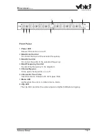
Page 5: ...ntrol the width of the selected frequency 4 Band Frequency Control To select the frequency to be adjusted 5 Channel Bypass Turns each channels EQ on or off 6 Channel Hi Pass Filter Used to select a channels 30 Hz hi pass filter 7 Mono LED Lights when the unit is in 6 band mono mode 8 Clip LED The clip LED monitors the units output and lights 3dB before clipping 1 3 4 5 2 6 7 8 ...

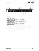
Page 6: ...sleeve ground ring signal and tip signal 3 Balanced Output XLR s 4dBu Wired pin 1 ground pin 2 ve and pin 3 ve 4 Balanced Output Jacks 10dBu Wired sleeve ground ring signal and tip signal 5 Mode Selector Selects 2 channels with 3 bands of EQ or 1 channel with 6 bands of EQ 6 Power Input IEC power input connector with fuse 230 VAC 50 Hz 1 2 3 4 3 4 5 6 ...

Page 7: ...ion for the MF section MF Frequency control This control selects the centre frequency for MF cut or boost and is adjustable from 200Hz to 8kHz HF gain control Sets the amount of cut or boost for the HF High Frequency section HF Frequency control This control selects the centre frequency for HF cut or boost and is adjustable from 500Hz to 20kHz HF Q control Varies the Q of the cut or boost region f...

Page 8: ...z Hi Pass filter now controls the whole unit Your input signal should now go to Channel 1 s input and the output taken from Channel 2 s output Channel 2 s input is disabled CHANNEL 2 Channel 2 s operation is identical to channel one except the input BYPASS and 30 Hz hi pass filter when used in mono mode TECHNICAL SPECIFICATIONS Input Electronically balanced 4dBu XLR 10dBu 1 4 TRS jack 20K ohm impe...

Page 9: ... detailed description of the fault and list any other equipment used in conjunction with the faulty product Send the fault description with the faulty product do not send it separately 2 Ensure safe transportation of your unit to the authorised service centre Ship it in the original factory packaging if possible 3 Do not ship the unit in any kind of rack Ignoring this warning may result in extensi...

Page 10: ...rective repairs upon receipt of the returned product Please save the original carton and all the packing materials in case shipping is required All products being returned to the factory or service centre for repairs must be shipped prepaid If the repairs made by Void or the Void Authorised Service Centre are not satisfactory the Owner is instructed to give written notice to Void If the defect or ...

Page 11: ...ranty is only valid in the country of purchase 2 That the product has not been abused or operated in conjunction with unsuitable or faulty apparatus 3 That the product has not been modified disassembled or tampered with by any person other than Void Acoustics technical staff 4 That the product has not suffered damage in transit Do not send goods to Void Acoustics without first obtaining a return a...

Page 12: ...ty Registration Thank you for purchasing this Void product Please complete this warranty registration card and cut off this part and send it to the address overleaf Date of purchase Model Serial number Suppliers name and address Post code Tel Your name and address Post code Tel ...

Reviews: