23
6.17
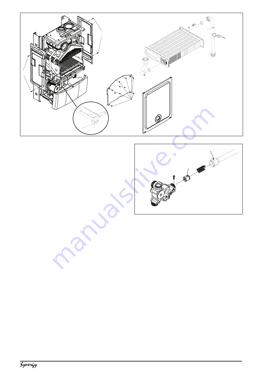
MAIN HEAT EXCHANGER (see fig. 27 & 29)
Carry out component removal procedure as
described in 6.4.
Fig. 27: unclip and remove the air chamber cover,
gently pull the cover towards you before lifting
and disengaging (2). Locate and remove the six
screws that secure the front combustion cover,
then remove the cover (3).
Fig. 29: remove the air chamber side panels if
necessary by unscrewing the securing screws
(3). Disconnect the flow and return connections
(4, 5) on the heat exchanger. The heat exchanger
can now be withdrawn from the appliance.
Replace in the reverse order. Ensure all seals
are in good condition, taking care to ensure they
are replaced correctly.
6.18
AIR PRESSURE SWITCH (see fig. 27 & 28)
Carry out component removal procedure as
described in 6.4.
Fig. 27: unclip and remove the air chamber cover,
gently pull the cover towards you before lifting
and disengaging (2).
Fig. 28: locate and remove the two screws (6)
holding the air pressure switch to the air chamber.
Disconnect the electrical connections and silicone
tubes (10) attached to the air pressure switch,
noting their positions. Replace in the reverse
order. Ensure all seals are in good condition,
taking care to ensure they are replaced correctly.
6.19
AUTOMATIC BYPASS (see fig. 30)
Carry out component removal procedure as
described in 6.4.
Disconnect and remove the flow pipe at the
heating manifold (1) and at the connection to the
air chamber. Using a hooked piece of wire,
carefully withdraw the bypass cartridge (2).
Ensure all seals are in good condition, taking care
to ensure they are replaced correctly. Replace in
the reverse order ensuring the cartridge is facing
the correct way.
Fig. 29
3
2
2
1
5
4
3
5
4
6.20
EXPANSION VESSEL fig. 1
Should the removal and replacement of the
expansion vessel be deemed impractical, an
external expansion vessel may be fitted to the
return pipe as close to the appliance as possible.
6.20.1 EXPANSION VESSEL REMOVAL (with
sufficient clearance above)
Carry out component removal procedure as
described in 6.4. Disconnect the flue from the
appliance. Disconnect the flexible expansion pipe
from the vessel (fig. 31). Locate and remove the
four screws that secure the vessel top holding
plate, remove the plate. The expansion vessel
can now be removed. Replace in the reverse
order. Ensure all seals are in good condition,
taking care to ensure they are replaced correctly.
6.20.2 EXPANSION VESSEL REMOVAL (with
insufficient clearance above)
Carry out component removal procedure as
described in 6.4. Disconnect the flue elbow or
pipe from the appliance flue outlet. Unclip and
remove the air chamber cover, gently pull the
cover towards you before lifting and disengaging.
Remove the RH side panel of the air chamber.
Disconnect the wiring to the fan, pressure switch,
primary thermistor & overheat thermostat.
2
1
Fig. 30


