

WARNING:
1. Opening the unit without prior permission
from Vollara will void its warranty coverage.
Contact Vollara at 1.800.989.2299 if you
have any questions.
2. Apply this unit to 120V AC 60Hz, single phase
load only.
3. The unit must be mounted vertically, in a dry
location, using the four provided mounting clips.
4. WARNING! THIS UNIT MUST BE INSTALLED
BY A LICENSED ELECTRICIAN (IN
COMPLIANCE WITH LOCAL ELECTRICAL
CODES). FAILURE TO DO SO COULD
RESULT IN DEATH OR SERIOUS INJURY.
5.
IMPORTANT!
This unit must be connected
directly to a dedicated circuit breaker. Do not,
under any circumstances, hard-wire install
without a dedicated breaker!
6. Proper installation of this unit requires
the dedicated breakers (two (2) single
pole, 20 amp breakers required) to be
installed in breaker positions 1 and 2 (upper
most positions in the breaker panel).
NOTE: If these positions are already in
use in your breaker panel, the electrician
must relocate the circuits that currently
occupy these positions (positions 1 and
2) to open positions located lower in the
breaker panel. FAILURE TO FOLLOW THIS
INSTALLATION PROCEDURE WILL VOID
YOUR WARRANTY !
YOU WILL NEED:
1. Two (2) dedicated, single pole, 20 amp circuit
breakers.
2. Appropriate tools including conduit.
3. A licensed electrician for installation.
MOUNTING THE STEADYPOWER FLUSH-
MOUNT (ECP240R)
WARNING! THIS UNIT MUST BE INSTALLED BY
A LICENSED ELECTRICIAN (IN COMPLIANCE
WITH LOCAL ELECTRICAL CODES). FAILURE
TO DO SO COULD RESULT IN DEATH OR
SERIOUS INJURY. DE-ENERGIZE POWER PANEL
(WE RECOMMEND TURNING OFF THE MAIN
POWER BREAKER) PRIOR TO BEGINNING THIS
PROCEDURE.
NOTE:
For surface mounted applications, you will
need a surface mounting adapter plate. See your
Vollara Independent Business Owner for more
information.
1. Inspect the exterior of the unit to ensure that it
has not been damaged in transit. Ensure that
the front label/overlay is still intact, and that
the cables protruding from the unit have not
been damaged.
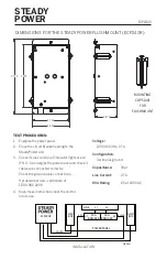
2. Place the back of the Flushmount Box against
wall where the unit is to be installed and trace
around its outside edge. Cut drywall along
traced line (dimension of traced area should
be approximately 4.866” wide by 8.250” high).
3. Run conduit (according to code) between the
conduit connector on the box and the power
panel, and feed the connection cables through
the conduit into the power panel.
4. Secure the four (4) clips to the mounting box
and tighten screws to tightly fit.
5. Screw Cover Plate onto unit.
INSTALLATION PROCEDURES:
1. De-energize power panel prior to connection
of the Steady Power unit (we recommend
turning off the Main Power Breaker).
2. Install the two (2) single pole, 20 amp circuit
breakers into circuit positions 1 and 2 (see
item 6 in “Warning Section” above) of the
circuit panel.
3. Connect the RED wire (L1) to the circuit
breaker located in position 1, the BLACK wire
(L2) to the circuit breaker located in position 2,
the GREEN with yellow stripe wire (Ground) to
the ground bus, and the WHITE wire (Neutral)
to the neutral bus, as shown in the diagram
on page 3.


