16
3.8 ASSEMBLING MACHINE
To assemble the machine parts, refer to the following steps:
NOTICE
Petrol-Gel sanitary lubricant or equivalent must be
used when lubrication of machine parts is specified.
NOTICE
The United States Department of Agriculture and
the Food and Drug Administration require that lu-
bricants used on food processing equipment be
certified for this use. Use lubricants only in accor-
dance with the manufacturer’s instructions.
A.
Assemble all o-rings onto parts dry, without
lubrication. Then apply a thin film of sanitary
lubricant to exposed surfaces of the o-rings.
B.
Lubricate the rear seal area on the auger shaft
with a thin layer of sanitary lubricant. Install the
rear seal o-ring. Lubricate the outside of the rear
seal o-ring with sanitary lubricant.
C.
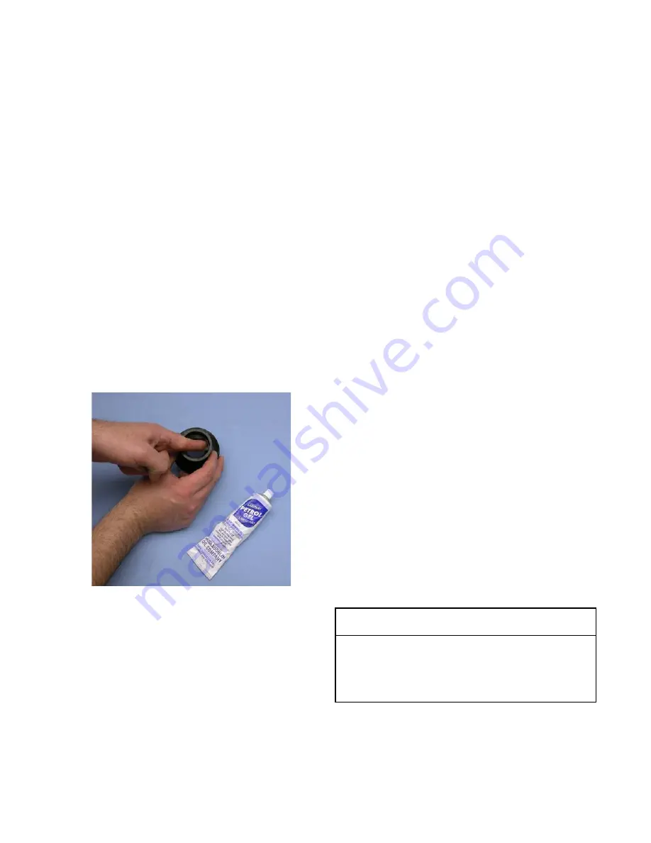
Install the stainless steel rear seal adapter into the
rear seal dry (without lubricant). Lubricate the
inside metal surface of the rear seal adapter and
install it onto the auger shaft. DO NOT lubricate the
outside of the rear auger seal (Fig. 3-6).
D.
Lubricate the hex drive end of the auger with a small
amount of spline lubricant. A small container of
spline lubricant is shipped with the machine.
E.
Screw the springs onto the studs in the plastic
flights. The springs must be screwed into the
flights completely to provide proper compression.
F.
Install the two plastic flights onto the rear of the
auger and insert it part way into the freezing
cylinder.
G.
Install the remaining plastic flights, push the auger
into the freezing cylinder and rotate slowly until the
auger engages the drive shaft.
H.
Apply a thin layer of sanitary lubricant to the inside
and outside of the auger support bushing. Install
the bushing onto the auger support and install the
auger support into the front of the auger. Rotate
the auger support so that one leg of the support
points straight up.
I.
Apply a thin layer of sanitary lubricant to the o-
rings on the spigot body and install the spigot body
through the bottom of the front door.
K.
Apply a thin film of sanitary lubricant to the door
seal o-ring and fit it into the groove on the rear of
the front door.
M.
Place the front door assembly on the mounting
studs and the push front door against the machine
carefully.
N.
Secure the front door to the machine by placing the
knobs on the studs and tightening until finger tight.
Do not overtighten. A proper o-ring seal can be
observed through the transparent front door.
3.9 SANITIZING
Sanitizing must be done after the machine is clean and just
before the machine is filled with mix. Sanitizing the night
before is not effective. However, you should always clean
the machine and parts after using it.
NOTE
The United States Department of Agriculture and
the Food and Drug Administration require that all
cleaning and sanitizing solutions used with food pro-
cessing equipment be certified for this use.
When sanitizing the machine, refer to local sanitary regu-
lations for applicable codes and recommended sanitizing
products and procedures. The frequency of sanitizing
must comply with local health regulations. Mix sanitizer
according to manufacturer’s instructions to provide a 100
parts per million strength solution. Mix sanitizer in quanti-
ties of no less than 2 gallons of 90°F to 110°F (32°C to
43°C) water. Allow sanitizer to contact the surfaces to be
sanitized for 5 minutes. Any sanitizer must be used only in
accordance with the manufacturer’s instructions.
A.
Prepare 2 gallons of sanitizing solution following
the manufacturer’s instructions.
B.
Install the mix inlet regulator into the hopper.
C.
Pour the sanitizing solution into the hopper.
Figure 3-6 Lubricate Rear Seal
CAUTION
Risk of Product Damage
Avoid prolonged contact of sanitizer with machine
parts. Sanitizer may cause corrosion of stainless
steel parts if there is prolonged contact.
Summary of Contents for Stoelting E131-OT2
Page 1: ...Model E131 OT2 F131 OT2 SERVICE MANUAL Manual No 513648 Rev 0 https appliancetechmanuals com ...
Page 2: ...https appliancetechmanuals com ...
Page 14: ...8 https appliancetechmanuals com ...
Page 16: ...10 https appliancetechmanuals com ...
Page 26: ...20 Figure 4 2 IntelliTec Control Menu Settings https appliancetechmanuals com ...
Page 52: ...46 8 2 AUGER SHAFT AND FACEPLATE PARTS https appliancetechmanuals com ...
Page 60: ...54 8 9 REFRIGERATION DIAGRAM WIRING DIAGRAM 01 2 3 3 3 3 https appliancetechmanuals com ...


