9
J.
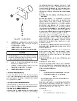
Do not operate the freezer when the MIX LOW
light is on or with less than 1-3/4 inches (4.4 cm)
of mix in the hopper. Refill the hopper immediately.
NOTE
The freezer has standby and sleep modes. When
the freezer is not used, after a preset number of
freezing cycles, it will enter the standby mode (fol-
lowed by sleep mode) and remain there until some-
one draws a product or presses the PUSH TO
FREEZE button. In the sleep mode, the freezer will
keep the product below 41°F (5°C). Sleep modes
are not to be used in place of cleaning and sanitiz-
ing. Frequency of cleaning and sanitizing is deter-
mined by Federal, State, and local regulatory agen-
cies.
3.5 MIX INFORMATION
Mix can vary considerably from one manufacturer to
another. Differences in the amount of butterfat content
and quantity and quality of other ingredients have a direct
bearing on the finished frozen product. A change in freezer
performance that cannot be explained by a technical
problem may be related to the mix.
Proper product serving temperature varies from one
manufacturer’s mix to another. Soft serve mixes generally
provide satisfactory product from 18° to 20°F (-7° to -6°C),
shake mixes 24° to 28°F (-4° to -2°C).
When checking the temperature, stir the thermometer in
the frozen product to read the true temperature.
Old mix or mix that has been stored at elevated tempera-
tures will produce poor-quality product with a bad taste and
unacceptable appearance. To retard bacteria growth in
dairy based mixes, the best storage temperature range is
between 36° to 40°F (2.2° to 4.4°C).
Some products tend to foam more than others. If foam
appears in the hopper, skim off with a sanitized utensil and
discard. Periodically, stir the mix in the hopper with a
sanitized utensil to help prevent excess foam.
3.6 REMOVING MIX FROM FREEZER
To remove the mix from the freezer, refer to the following
steps:
A.
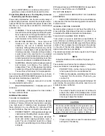
Remove the mix inlet regulator from the hopper by
pulling straight up.
B.
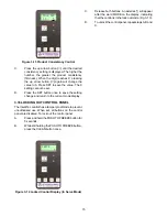
Press the CLEAN button to rotate the auger. Allow
the mix to agitate in freezer barrel until the mix has
become a liquid, about 5 minutes.
C.
Drain the liquid mix by opening the spigot. A
bucket or container should be placed under the
spigot to catch the liquid mix.
D.
Place the Main Freezer Power OFF-ON switch in
the OFF position.
3.7 CLEANING THE FREEZER
NOTE
The frequency of cleaning the freezer and freezer
parts must comply with local health regulations.
After the mix has been removed from the freezer, the
freezer must be cleaned. To clean the freezer, refer to the
following steps:
A.
Fill the hopper with 2 gallons (7.5 liters) of tap
water.
B.
Place the Main Freezer Power OFF-ON switch in
the ON position and press the CLEAN switch. The
auger will start to rotate.
C.
Allow the water to agitate for approximately 30
seconds.
NOTE
If freezer is left in CLEAN for more than 20 minutes,
the display will show an error code. To reset, place
the Main Freezer Power OFF-ON switch in the OFF
position and back in the ON position.
D.
Open the spigot to drain the water. Remember to
place a container under the spigot to catch the
water. When the water has drained, place the
switch in the OFF position. Allow the freezing
cylinder to drain completely.
E.
Prepare detergent water by mixing 2 oz. of
Palmolive detergent or equivalent in 2 gallons of
90° to 110°F (32° to 43°C) water. Repeat steps A
through D using the detergent solution.
3.8 DISASSEMBLY OF FREEZER PARTS
CAUTION
Hazardous Moving Parts
Revolving auger shaft can grab and cause injury.
Place the Main Freezer Power OFF-ON switch in
the OFF position before disassembling for cleaning
or servicing.
Inspection for worn or broken parts should be made each
time the freezer is disassembled. All worn or broken parts
should be replaced to ensure safety to both the operator
and the customer and to maintain good freezer perfor-
mance and a quality product. Check the wear line on the
auger flights on a regular basis (Fig. 3-6) and replace as
needed. Frequency of cleaning must comply with the local
health regulations.
Summary of Contents for Stoelting O111I
Page 1: ...Model O111I OPERATORS MANUAL Manual No 513588 1 Sept 2006...
Page 2: ......
Page 22: ...16...
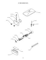
Page 28: ...22 O111 REPLACEMENT PARTS...
Page 30: ......


