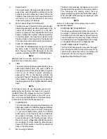
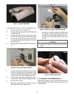
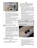
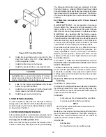
background image

14

2.

Remove the drip tray by gently lifting up to
disengage from the support and pulling out. Clean
behind the drip tray and front of the freezer with a
soap solution.

D.

QUARTERLY

WARNING

High voltage will shock, burn or cause death. Turn
off and lock out main power disconnect before ser-
vicing. Do not operate machine with panels re-
moved.

The air-cooled condenser is a copper tube and aluminum
fin type. Condensing is totally dependent upon airflow. A
plugged condenser filter, condenser, or restrictions in the
louvered panel will restrict airflow. This will lower the
capacity of the system and damage the compressor.

The condenser must be kept clean of dirt and grease. The
freezer must have a minimum of 3” (7.5 cm) of ventilation
on the right and left sides of the unit for free flow of air.
Make sure the freezer is not pulling over 100° F (37° C) air
from other equipment in the area.

The water-cooled condenser is a tube and shell type. The
condenser needs a cool, clean supply of water to properly
cool the freezer, inlet and discharge lines must be 3/8” I.D.
minimum.

The condenser and condenser filter require periodic clean-
ing. To clean, refer to the following procedures.

1.

Remove the Phillips head screw from the bottom
of the right side panel, and then slide the panels
down and out.

2.

To remove the condenser filter, grasp the top and
pull off. Visually inspect for dirt. If the filter is dirty,
shake or brush excess dirt off the filter and wash
in warm, soapy water. Once the filter is clean rinse
thoroughly in warm, clear water and shake dry,
taking care not to damage the filter in any way
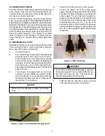
(Figure 28).

3.

Visually inspect the condenser for dirt by shining
a light through the coil from the back (inside) of the
condenser.

4.

If the condenser is dirty, place a wet towel over the
front (outside) of the condenser.

5.

Using a vacuum, carefully clean the condenser
coil from the inside and outside of the freezer. A
stiff bristled brush may help in releasing debris
from between the condenser coils.

E.

SEMI-ANNUALLY

1.

Check drive belt for proper tension. Push belt in
with one finger, belt should deflect about 3/8".

2.

Lubricate condenser fan motor with S.A.E. 20
weight oil. Three to six drops is required.

CAUTION

Do not over-lubricate; resulting damage could cause
motor failure.

3.14 EXTENDED STORAGE

Refer to the following steps for storage of the freezer over
any long period of shutdown time:

A.

Turn the Main Freezer Power OFF-ON switch to
the OFF position.

B.

Disconnect (unplug) from the electrical supply
source.

C.

Clean thoroughly with a warm water detergent all
parts that come in contact with the mix. Rinse in
clean water and dry parts. Do not sanitize.

NOTE

Do not let the cleaning solution stand in the hopper
or in the freezer barrel during the shutdown period.

D.

Remove, disassemble and clean the front door,
mix inlet regulator and auger parts. Place the
auger flights and the front auger support bushing
in a plastic bag with a moist paper towel to prevent
them from becoming brittle.

E.

In a water cooled freezer, disconnect water lines
and drain water. With a flathead screwdriver, hold
the water valve open and use compressed air to
clear the lines of any remaining water.

3.15 PRODUCT CONSISTENCY ADJUSTMENT

The IntelliTec control monitors the consistency (firmness)
of the product (mix) in the freezing cylinder by monitoring
the drive motor amp draw. When consistency is reached,
the drive motor and refrigeration system will shut off. The
control panel on the front of the freezer allows the operator
to adjust the freezing cylinder to create the desired product
consistency.

A.

Place the FREEZING CYLINDER OFF/ON switch
in the ON position.

B.

Press the SET button on the Control Panel once.
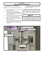
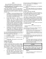
Fine Adj will appear on the LCD screen (Fig. 3-
12).

Summary of Contents for Stoelting O111I

Page 1: ...Model O111I OPERATORS MANUAL Manual No 513588 1 Sept 2006...

Page 2: ......

Page 3: ...built prior to date of change DO NOT ATTEMPT to operate the machine until instructions and safety precautions in this manual are read completely and are thoroughly understood If problems develop or q...

Page 4: ...ecific safety information the following safety defini tions are provided to assist the reader The purpose of safety symbols is to attract your at tention to possible dangers The safety symbols and the...

Page 5: ...Operation 8 3 5 MixInformation 9 3 6 Removing Mix From Freezer 9 3 7 Cleaning The Freezer 9 3 8 Disassembly of Freezer Parts 9 3 9 Cleaning The Freezer Parts 10 3 10 Sanitize Freezer and Freezer Parts...

Page 6: ...reezerControls 5 3 2 IntelliTecControl 7 3 3 Mix Inlet Regulator 7 3 4 SanitizingHopper 8 3 5 DuringFreezingCycle 8 3 6 Auger Flight Wear 10 3 7 RemovingAugerSupport 10 3 8 RemovingAugerShaftandFlight...

Page 7: ...zer is designed to operate with almost any type of commercial soft serve or non dairy mix available including ice milk ice cream yogurt and frozen dietary desserts This manual is designed to assist qu...

Page 8: ...ltage AC 1 PH 208 230V Total Run Amps 13 00 DriveMotor 1 5 HP Use 20 amp HACR circuit breaker Automatic safeguard circuit built into electronic control protects major freezercomponentsunderabnormalope...

Page 9: ...ronment Thelabelshavebeendesignedtowithstand washingandcleaning Alllabelsmustremainlegibleforthe lifeofthefreezer Labelsshouldbecheckedperiodicallyto be sure they can be recognized as warning labels I...

Page 10: ...levelthefreezerbyturningthebottom part of each leg in or out Then separate freezer base gasket and install with seam to the back and angle to the top C If the freezer is equipped with an air cooled c...

Page 11: ...repair or perform maintenance on the freezer until the main electrical power has been disconnected G Donotoperateunderunsafeoperatingconditions Never operate the freezer if unusual or excessive noise...

Page 12: ...are flashing the freezer is in an error condition If the LCD displays an error turn the Main Freezer Power OFF ON switch to the OFF posi tion correct the problem Refer to Troubleshooting in Section 4...

Page 13: ...E When sanitizing the freezer refer to local sanitary regula tions for applicable codes and recommended sanitizing products and procedures The frequency of sanitizing must comply with local health reg...

Page 14: ...ill automatically fill until it is about 1 2 full If freezer barrel does not fill check for obstruction in the mix inlet regulator If freezer barrel fills over 1 2 full indicated by low overrun check...

Page 15: ...erby pulling straight up B PresstheCLEANbuttontorotatetheauger Allow themixtoagitateinfreezerbarreluntilthemixhas become a liquid about 5 minutes C Drain the liquid mix by opening the spigot A bucket...

Page 16: ...springs G Keep the rear of the auger shaft tipped up once it is clear of the freezer to avoid dropping rear seal H Remove the rear seal I Wipe socket lubricant from the drive end rear of the auger wi...

Page 17: ...on of parts is specified NOTE The United States Department of Agriculture and the Food and Drug Administration require that lu bricants used on food processing equipment be cer tified for this use Use...

Page 18: ...ts Fats are difficult to remove and help attribute to milkstone buildup MILKSTONE Is a white gray film that forms on equip mentandutensilsthatcomeincontactwithdairyproducts Thesefilmswillaccumulateslo...

Page 19: ...t ideal for two reasons 1 PRODUCTSAFETY Strongacidsaredangerous chemicals and handling them requires safety 2 MACHINE DAMAGE Strong acids will attack metal and rubber causing premature wear of parts T...

Page 20: ...eloverthe front outside of the condenser 5 Using a vacuum carefully clean the condenser coil from the inside and outside of the freezer A stiff bristled brush may help in releasing debris from between...

Page 21: ...ONTROL PANEL The IntelliTec control has a tamper proof mode to prevent unauthorized use When set all buttons on the control panel are disabled To lock out the control panel A Press and hold the PUSH T...

Page 22: ...16...

Page 23: ...e product does not reach proper temperature in Sleep 2 Mode This error is generally caused by very low mix levels in the freezer smixcontainerorfromproductbreakdown Another common cause results from a...

Page 24: ...ror Code 8 Cab Sensor A Cab Sensor Error E8 will not occur on the E111 or F111 freezer Error Code 9 High Pressure Cutout High Pressure Cutout Errors E9 are usually caused by a dirty or inefficient con...

Page 25: ...s in mix are broken down 6 Auger is assembled wrong 7 Refrigeration problem 1 A minimum of 3 inches of vent space required See Section 2 2 Change location or direct hot air away from freezer 3 Clean S...

Page 26: ...Rear auger seal leaks 1 Outside surface of rear auger seal is lubricated 2 Rear seal missing or damaged 3 Seal o ring missing damaged or installed incorrectly 4 Worn or scratched shaft 1 Clean lubric...

Page 27: ...ion Electrical Shock 324106 Decal Caution Electrical Wiring Materials 324107 Decal Caution Hazardous Moving Parts 324141 Decal Caution Rotating Blades 324208 Decal Attention Refrigerant Leak Check 324...

Page 28: ...22 O111 REPLACEMENT PARTS...

Page 29: ...Pack 2 624677 5 O Ring Mix Inlet Black 5 Pack 2 624678 5 O Ring Rear Seal Black 5 Pack 1 625133 O Ring Front Door Red 1 666786 Seal Rear Auger Black 1 694255 Spring Auger Flight 5 744276 Tray Drain 1...

Page 30: ......

Page 31: ...ons remedies are subject to the conditions that Buyer a signs and returns to Stoelting upon installation the Start Up and Training Checklist for the affected equipment b gives Stoelting prompt written...

Reviews: