28
• Up to two circuit breakers may also be installed in the housing of the temperature controller. Alternatively, an operat
-
ing hours counter or energy cost meter may be installed as well. Installation also requires a piece of top-hat rail that
must be screwed to the housing bottom of the temperature controller (neither of these components is enclosed).
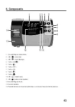
For this, remove the rectangular cover (see figure in chapter 6, item 14), which is attached to the top of the housing
with two small screws.
Wiring of the outputs of the temperature controller with the circuit breakers or the operating hours counter or
energy cost meter must be performed according to your own discretion. Observe the operating instructions
of the products used by you.
In any case, ensure that all cables are mechanically secured in the housing, e.g. by cable clips.
• Tighten the cap nuts of the three cable feedthroughs to ensure proper tension relief of the cables.
• Attach the housing top to the housing bottom again. Place the cover (see chapter 6, item 14) in the proper alignment
between the two housing parts.
• Attach the housing top on the housing bottom with four screws. Ensure that the cables are not crushed.
• Push the small cover in at the right side of the temperature controller.
• Fold the cover on the left side of the temperature controller down until it latches.
• Fasten the temperature sensor in a suitable location. Keep sufficient distance from the cooling or heating unit,
since there may be wrong measurements otherwise, which will make control of the temperature by the temperature
controller impossible. Protect the cable between the temperature controller and the temperature sensor from sharp
edges; do not route the cable through door seals.
d) Commissioning
• After screwing the housing shut properly, switch on the mains voltage.
• All display segments will appear briefly, followed by display of the temperature measured by the temperature sensor.
Then the clock starts.
Now perform programming; see description in the next chapter.


