44
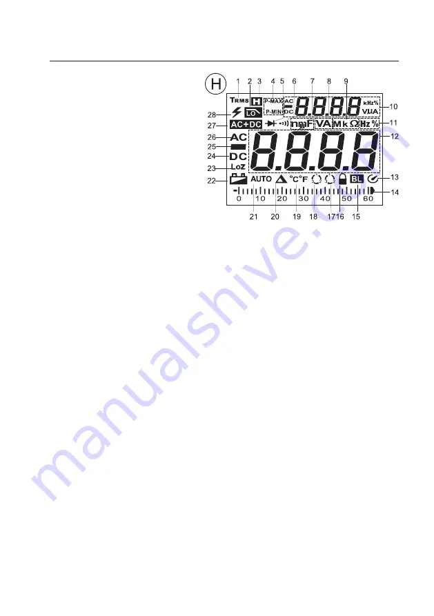
8. Display Indications and Symbols
The following symbols and information are present
at the device or in the display.
1 True root mean square
2 Symbol for active low-pass filter “LPF”
3 Hold function is active
4 Symbols for measured value storage
P = Top value (Peak)
MAX = Maximum value
MIN = Minimum value
5 Symbol for the diode test
6 Symbol for the acoustic continuity tester
7 Symbol for nano (n, exp.-9)
Symbol for milli (m, exp.-3)
Symbol for micro (µ, exp.-6)
Farad (F, unit of electric capacity)
8 Volt (V, unit of electric voltage)
Ampere (A, unit of electric current)
9 Symbol for mega (M, exp.6)
Symbol for kilo (k, exp.3)
Ohm (unit of electric resistance)
10 Subdisplay (auxiliary display)
11 Hertz (Hz, unit of frequency), display of the pulse duration ratio (%)
12 Measured value display
13 Automatic deactivation is activated
14 Bar chart, analogue bar display for the digital value
15 Automatic lighting for display is active
16 Lock icon for phase recognition (flashing = detection mode, permanent display = phase recognised)
17 3-Phase rotating direction display “right turning”
18 3-Phase rotating direction display “left-turning”
19 Symbol degrees Celsius, symbol degrees Fahrenheit; measuring function is not present
20 Delta symbol for relative value measuring (= reference value measuring)
21 Automatic measurement range selection is active
22 Battery change display


