45
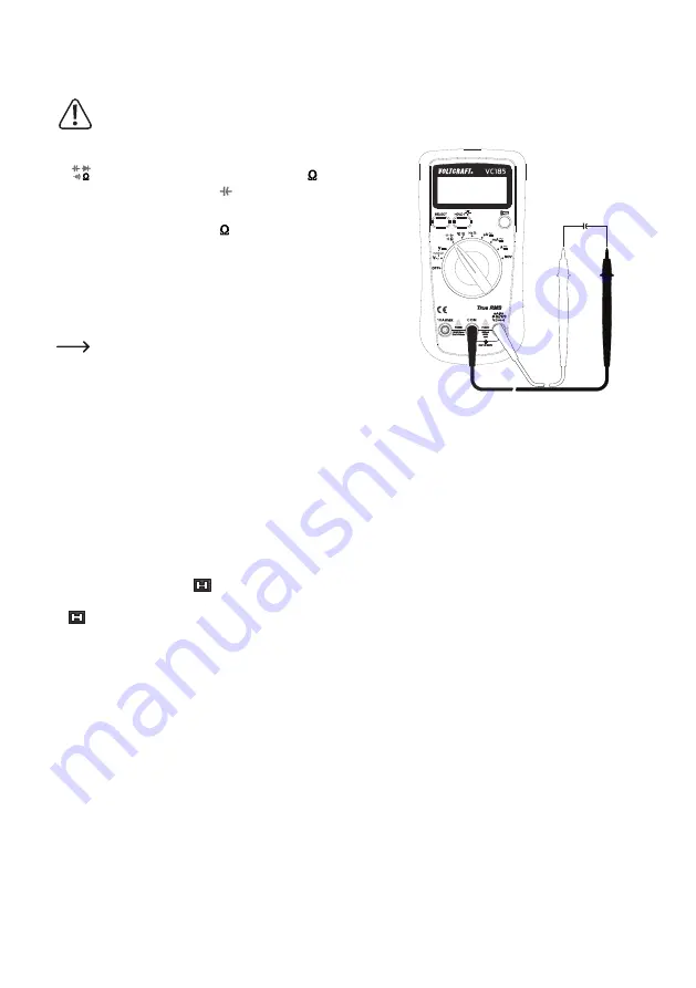
d) Capacitance measuring
Make sure that all the circuit parts, switches and components and other objects of measurement are
disconnected from the voltage and capacitors are discharged.
• Turn the digital multimeter on and select the measuring setting position
“
” with the rotary switch (5). “M” and the “ ” unit symbol are
displayed in the LC display (4).
• Resistance measuring in auto-mode is selected by default and
cannot be switched off. The symbol and M for mega indicate
resistance measuring mode appear in the LC display (4). To select the
capacitance testing mode, press the SELECT button (1) twice until the
“nF” capacitance unit symbol appears in the LC display (4).
• Insert the red measuring lead into the V socket (8) and the black
measuring lead into the COM socket (9).
Make sure you disconnect all power sources, discharge all
capacitors and isolate the component to be measured from
other components in a circuit before taking any measurements.
• Now connect the two measuring prods to the capacitor to be measured
with the correct polarity. The red measuring tip indicates the positive
pole, the black measuring tip the negative pole.
• A reading will be displayed. Wait until the displayed value has stabilised.
•
If the tested capacitor is shorted, or its capacitance is over the specified
measuring range the “OL” symbol will be displayed on the LC display.
• When measuring large capacitors, which normally is a capacitance
value of >40 μF, it may take a few seconds until the reading has
stabilized.
• Press the HOLD button (12) in order to lock the measured value if
needed. The hold symbol appears in the LC-display (4). Press the
HOLD button (12) in order to release the locked value. The hold symbol
disappears from the LC-display (4).
• After measuring, remove the measuring leads from the measuring
object and turn the digital multimeter off. Turn the rotary switch (5) to
the position “OFF”.
C


