48
g) Frequency and duty ratio measurements
Do not exceed the maximum permitted input values. Do not touch any circuits or parts of circuits if
they may be subject to voltages higher than 25 V/AC rms or 35 V/DC! Danger to life!
The maximum permissible voltage in the circuit must not exceed 600 V in CAT III.
The digital multimeter can be used to measure and indicate signal voltage frequencies from 10 Hz to 10 MHz
(auto range): Observe that the maximum values (also see chapter 14. Technical Data) must not be exceeded while
measuring.
Proceed as follows to measure frequencies:
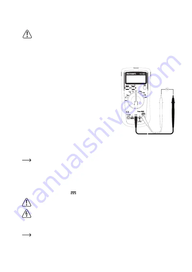
• Turn the digital multimeter on and select “Hz %” measurement using
the rotary switch (5).
• Auto-mode is selected by default and cannot be switched off. The “Hz”
symbol indicating the frequency measuring mode appears on the LC
display (4).
•
Insert the black measuring lead into the COM socket (9) first. Then
insert the red measuring lead into the V socket (8).
• Connect the two measuring prods to the object to be measured (signal
generator, circuit, etc.). The black test lead is connected first, the red
test lead second. The positioning of the prods is arbitrary.
• The frequency reading and the corresponding unit (Hz) are displayed.
• To measure the duty ratio, select the corresponding display by pressing
the SELECT button (1) once. The percent “%” symbol appears in the
LC display (4).
• Read the measurement in the LC display (4). A positive symbol (+)
indicates POSITIVE time percent voltage measurement. A negative
symbol (-) indicates NEGATIVE time percent voltage measurement.
A positive reading typically indicates a circuit’s ON time and a
negative reading its OFF time. On occasion a negative portion
of the signal can create an ON signal.
• After measuring, remove the leads from the measuring object in
reverse order: red first, then black and turn the digital multimeter off.
h) Current measuring (A and AC~)
The voltage in the measuring circuit may not exceed 600 V.
Measuring operations of >5 A may only be performed for at most 10 seconds with a subsequent
measuring pause of 15 minutes.
All current measuring ranges are provided with fuses and thus protected against overload.
Proceed as follows to measure DC currents “µA, mA, A”
Always start current measurements at the highest measurement range and switch down to lower ranges if
necessary. Before changing the measurement range, always power down the circuit. All current measuring
ranges are secured with fuses and thus protected against overload.


