89
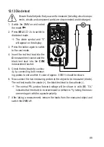
12.13 Diode test
Ensure that all objects that you want to measure (including circuit compo-
nents, circuits and component parts) are disconnected and discharged.
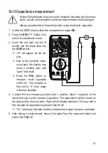
1. Switch the DMM on and select
the mode.
2. Press
SEL
/
2x to switch to
diode test mode.
Æ
The diode symbol and “V”
will appear on the display.
3. Press the button again to switch
to the next mode.
4. Insert the red test lead into the
Ω
measurement socket and the
black test lead into the
COM
measurement socket.
5. Check the test leads for continu-
ity by connecting both measur-
ing probes to one another. A value of approx. 0.000 V should be shown.
6. Now connect the two measuring probes to the object to be measured (diode).
The red test lead to the anode (+), the black test lead to the cathode (-).
Æ
The normal PN junction forward voltage will be shown in volts
(V)
. “OL”
indicates that the diode is reverse-biased or defective. Try taking the meas-
urement again with the opposite polarity.
7. After taking a measurement, remove the leads from the measured object and
switch the DMM off.


