67
p) Continuity Test
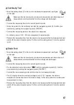
• Move the setting wheel (7) to the icon for resistance measurement, see figure
on the right.
Make sure that all circuit parts, circuits and components and other objects of
measurement are disconnected from the voltage and discharged.
• Connect the measuring lines to the current injection probe.
• Select the symbol for the continuity test with the navigation joystick (5). Confirm your
selection by pushing the navigator joystick (“ENTER”).
• Connect the measuring prods to the object to be measured.
• A continuity value of <30 - 100
Ω
is recognised. A signal sounds.
• Remove the measuring lines from the object to be measured after the measurement and
switch off the current injection probe. For this, turn the setting wheel (7) into the position
“OFF”.
q) Diode Test
• Move the setting wheel (7) to the icon for resistance measurement, see figure
on the right.
Make sure that all circuit parts, circuits and components and other objects of
measurement are disconnected from the voltage and discharged.
• Connect the measuring lines to the current injection probe.
• For the diode test, select the symbol “
” with the navigation joystick (5). Confirm
your selection by pushing the navigator joystick (“ENTER”).
• Connect the two measuring prods with the object to be measured (diode).
• The LC display shows the continuity voltage in volt. If “OL” appears, the diode is
measured in reverse direction or the diode is faulty. In this case, perform a counter-pole
measurement to check.
• Remove the measuring lines from the object to be measured after the measurement and
switch off the current injection probe. For this, turn the setting wheel (7) into the position
“OFF”.

