43
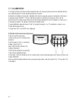
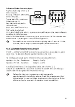
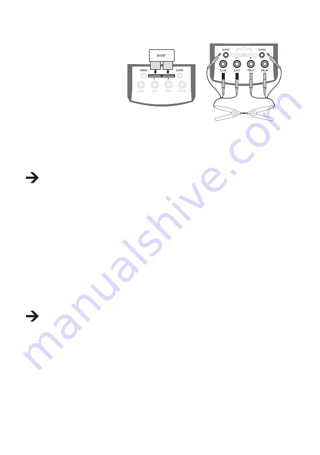
Calibration with closed measuring inputs:
Plug the calibration plug “SHORT” (19)
into the integrated
measuring terminals or short-circuit the
two measuring lines.
Push the button “CAL”. A countdown
display counts from 30
down. After the time elapses, the
status is displayed.
“PASS” partial calibration successful.
“FAIL” partial calibration failed.
In this case, check all contact points for contamination and possible damage at the measuring lines and
repeat the entire calibration process.
After successful calibration with closed measuring inputs, push the button “CAL”. The calibration mode
is terminated and the measuring device returns to measuring operation.
The calibration process can be cancelled with the operating button (2) at any time. Calibra-
tion should, however, always be performed completely and without interruption.
7.8. EQUIVALENT SWITCHING CIRCUIT
In “AUTO-L”, “AUTO-C” and “AUTO-R” operation, the measuring functions are recognised as serial or
parallel circuit. This depends on the entire equivalent impedance of the circuit.
The following parameters are used for differentiation in the serial and parallel circuits:
Impedance > 10 kOhm Parallel mode
Display Lp, Cp or Rp
Impedance < 10 kOhm Serial mode
Display Ls, Cs or Rs
Serial and parallel modes can be manually switched with the button “SER/PAL” (11).
Each push switches the function. The auto mode is switched off. To switch on the auto mode again,
select the desired measuring function with the button „FUNC“ (3).
Real capacities, inductivities or resistors are no ideal components for
measuring the pure blind and effective resistance. Usually effective resistance and blind
resistance exist at the same time. Suitable impedance can be simulated with an effective
resistance and another component (coil, capacitator) in serial or parallel circuit.


