30
4. Push the on/off button (6) to turn on the product. All display elements will light up
briefly. An eight second countdown follows, after which the device is operational.
5. Hold the sensor head (1) into the area you wish to measure. The real-time
measurement readings appear on the display (13):
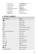
- Upper half of display: airflow velocity (VEL)
- Lower half of display: volume flow (FLOW) or temperature (TEMP)
Two arrows are imprinted on the sensor head at the level of the hot-wire sensor.
During measurement, hold the sensor head so that the arrows point in the
direction of airflow.
6. Push the FLOW TEMP button (8) to switch between displaying volume flow and
temperature in the lower half of the display.
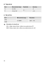
The airflow's cross sectional area must be entered in order for the meter to
correctly calculate volume flow. Refer to the chapter "Settings".
Should one of the multipliers (X10 or X100) appear beneath the reading, multiply
the reading by this multiplier to receive the correct measurement value.
7. After use, push the metallic protective sleeve (2) back over the sensor head to
protect the hot-wire sensor and the thermistor.
8. Turn off the meter, disconnect the telescopic hot-wire sensor (4) from the meter and
collapse the telescopic rod.
b) MAX/MIN function
• Repeatedly push the MAX/MIN button (9) during measuring to switch between
displaying the maximum and minimum measured values. The corresponding
indicator (REC MAX or REC MIN) is shown at the bottom of the display (13).
• Push and hold the MAX/MIN button for approx. one second to return to displaying
the real-time measured value.
Summary of Contents for PL-135 HAN
Page 6: ...6 3 Bedienelemente 1 2 3 14 13 7 10 8 11 9 12 6 5 4 ...
Page 24: ...24 3 Operating elements 1 2 3 14 13 7 10 8 11 9 12 6 5 4 ...
Page 42: ...42 3 Eléments de fonctionnement 1 2 3 14 13 7 10 8 11 9 12 6 5 4 ...
Page 60: ...60 3 Bedieningselementen 1 2 3 14 13 7 10 8 11 9 12 6 5 4 ...
Page 75: ...75 ...


