background image

16

Intended Use

The laboratory power unit is a combination of direct current power unit and safety variable isolating trans-
former with alternating current output. The device can be set up as a table device or integrated into rack
systems.
The DC voltage source is used for operating low-voltage consumers. A variable output with adjustable
voltage and current and a fixed voltage output with fixed current limitation are available. Connection is
possible on the front and rear alike.
The AC variable isolating transformer serves as galvanic separator for work on grid-voltage powered
electrical devices. The AC output voltage can be adjusted infinitely. 
When switching the DC outputs of several DC power units in series, voltages of >75 V/DC, which are dan-
gerous to contact, may be generated. At the AC output, voltages of >50 V/AC can be generated accor-
dingly. Starting at these voltages, insulated lines/measuring cables must be used for safety reasons.
DC connection on the front is performed with 4 mm safety sockets, on the rear with socket screw
connectors. The outputs (front and back) are connected to each other.
The AC output is connected through a potential-free socket without grounding contact. For measuring
purposes, suitable measuring adapters must be used. 

Only 1 device at a time may be connected to the AC output. Never use any multiple
outlets, since the grid voltage can be transferred to the other devices through the
grounding contact in case of an error. Danger to life!
Unisolated lines or open contacts must be avoided under all circumstances. Danger
of electrical shock when touching two live conductors!
The connection cables used must be large enough. Where the conductor section is
too small, overheating and fire may result.

The output data is as follows:
Output 1 “DC OUTPUT”

0 - 30 VDC, 0 - 5 A

Output 2 “5V/3A”.

5 VDC max. 3 A

Output 3 “AC OUTPUT”

0 - 250 VAC max. 4.5 A (max. 1125 VA)

The voltage and current on output 1 and current on output 3 can be set infinitely variable through the
rotary control. The values are displayed on the respective LC displays.
The device is overload- and short-circuit-protected. The alternate voltage output is protected by a cir-
cuit breaker.
The laboratory power unit is designed in compliance with protection class 1. It is only approved for
connection to shockproof sockets with protective grounding and an alternating current of 230V/AC
commonly used in households. All outputs are potential-free.
Operation is impermissible under unfavourable ambient conditions. Unfavourable ambient conditions are:
- moistness or high humidity
- dust and combustible gases, vapours or solvents
- thunderstorms or similar conditions such as strong electrostatic fields etc.
Any use other than that described above will damage the product and may involve other risks, such as
short-circuit, fire, electric shock, etc. Do not change or modify any part of the product! 
The safety instructions must be observed under all circumstances!

Summary of Contents for PS-1305-230

Page 1: ...4 Laboratory Power Unit PS 1305 230 OPERATING INSTRUCTIONS Page 15 25 Alimentation de laboratoire PS 1305 230 NOTICE D EMPLOI Page 26 36 Laboratoriumvoeding PS 1305 230 GEBRUIKSAANWIJZING Pagina 37 47 Best Nr Item No N de commande Bestnr 51 23 23 Version 05 10 ...

Page 2: ...es in technology and equipment reserved Copyright 2010 by Voltcraft Informations légales dans nos modes d emploi Ce mode d emploi est une publication de la société Voltcraft Lindenweg 15 D 92242 Hirschau Allemagne Tél 49 180 586 582 7 www voltcraft de Tous droits réservés y compris de traduction Toute reproduction quelle qu elle soit p ex photocopie microfilm saisie dans des installations de trait...

Page 3: ... of contents with the corresponding page numbers can be found in the index on page 15 Ce mode d emploi appartient à ce produit Il contient des recommandations en ce qui concerne sa mise en service et sa manutention Veuillez en tenir compte et ceci également lorsque vous remettez le produit à des tiers Conservez ce mode d emploi afin de pouvoir vous documenter en temps utile Vous trouverez le récap...

Page 4: ......

Page 5: ...tnis Wir sind uns sicher Ihr Start mit Voltcraft ist zugleich der Beginn einer langen und guten Zusammenarbeit Viel Spaß mit Ihrem neuen Voltcraft Produkt Inhaltsverzeichnis Einführung 4 Lieferumfang 4 Bestimmungsgemäße Verwendung 5 Bedienelemente 6 Sicherheits und Gefahrenhinweise 7 Funktionsbeschreibung 8 Inbetriebnahme 9 Auswahl der Netzspannung 9 Anschluss des Netzkabels 9 Aufstellen des Gerät...

Page 6: ...erfall ggf die Netzspannung über den Schutzleiterkontakt auf die anderen Geräte übertragen werden kann Lebensgefahr Unisolierte Leitungen oder offene Kontakte sind unbedingt zu vermeiden Strom schlaggefahr bei Berührung zweier spannungsführender Leitungen Es müssen ausreichend dimensionierte Anschlusskabel verwendet werden Ein zu geringer Leiterquerschnitt kann zur Überhitzung und zum Brand führen...

Page 7: ...öffnungen für Rack Systeme 11 Netzschalter zur Inbetriebnahme I Ein 0 Aus 12 Sicherungsautomat für AC Ausgang 13 Potentialfreie AC Steckdose ohne Schutzleiterkontakte 14 Festspannungsausgang 5VDC Pluspotential rot Minuspotential blau 15 DC Ausgang regelbar Pluspol rot Minuspol blau Erdpotential gelb grün 16 Tragegriffe 17 Schutzkontakt Kaltgeräteanschluss für Netzkabel 18 Eingangswahlschalter für ...

Page 8: ...nen besondere Tipps und Hinweise zur Bedie nung gegeben werden sollen Nur zur Verwendung in trockenen Innenbereichen Dieses Gerät ist CE konform und erfüllt die erforderlichen nationalen und europäischen Richtlinien Schutzleiteranschluss diese Schraube darf nicht gelöst werden Erdpotential Massepotential Elektrogeräte und Zubehör sind keine Spielzeuge und gehören nicht in Kinderhände In gewerblich...

Page 9: ...eb zu sichern Es ist anzunehmen dass ein gefahrloser Betrieb nicht mehr möglich ist wenn das Gerät sichtbare Beschädigungen aufweist das Gerät nicht mehr arbeitet und nach längerer Lagerung unter ungünstigen Verhältnissen oder nach schweren Transportbeanspruchungen Beachten Sie auch die Sicherheitshinweise in den einzelnen Kapiteln bzw in den Bedienungsanlei tungen der angeschlossenen Geräte Funkt...

Page 10: ...en schalten Sie es aus und trennen es vom Netz Die Anzeigen bleiben nach dem Ausschalten noch einige Sekunden an um die internen Kondensatoren zu entladen Auf einen ausreichenden Leiterquerschnitt der Anschlussleitungen ist unbedingt zu achten da eine Überlastung zum Leitungsbrand führen kann Auswahl der Netzspannung Das Labornetzgerät kann wahlweise mit 115 V oder mit 230 V AC betrieben werden St...

Page 11: ...gangsbuchsen und 15 mit einem Verbindungskabel mind 1 0 mm2 Der Ausgang wird kurzgeschlossen Im Display AMPERE 2 kann der Stromwert abgelesen werden Die Anzeige CC leuchtet während der Einstellung Über den Drehregler AMPERE 1 kann die max Stromstärke Strombegrenzung eingestellt werden Entfernen Sie nach erfolgter Einstellung die Kurzschlussbrücke Das Display zeigt wieder die tatsäch liche Stromstä...

Page 12: ...Kurzschluss zu schützen Im AC Bereich ist ab einer Spannung 50 V die Verwendung schutzisolierter Leitun gen und Anschlusskabel vorgeschrieben Achten Sie auf einen ausreichenden Leiterquerschnitt für die vorgesehene Strom stärke Am Netzgerät sind die DC Ausgänge doppelt vorhanden 15 und 20 sowie 14 und 21 Diese Ausgän ge sind miteinander Verbunden und führen immer die selbe Ausgangsspannung Entfern...

Page 13: ...s Reinigungstuch ohne scheuernde chemische und lösungsmittelhaltige Reinigungsmittel Primäre Netzsicherung wechseln Lässt sich das Labornetzgerät nicht mehr einschalten so ist vermutlich die primäre Netzsicherung 9 defekt Zum Auswechseln der Netzsicherung gehen Sie wie folgt vor Schalten Sie das Netzgerät aus und entfernen alle Anschlusskabel und den Netzstecker vom Gerät Schrauben Sie den Sicheru...

Page 14: ...lieren Sie die Sekundärsicherung 12 am AC Ausgang Die CC Anzeige 3 leuchtet DC Konstantstrombetrieb Die voreingestellte Stromstärke wurde überschritten Kontrollieren Sie die Stromaufnahme an Ihrem Verbraucher und erhöhen Sie ggf die Strombegrenzung am Netzgerät Die CV Anzeige 3 leuchtet Konstantspannungsbetrieb Das Netzgerät arbeitet normal Am Ausgang wird die eingestellte konstante Spannung ausge...

Page 15: ...t 1 mVrms 10 mV 3 mArms Regelverhalten bei 100 5 mV 10 mV Laständerung 7 mA Regelverhalten bei 3 mV 10 mV Netzschwankung 5 mA Betriebsspannung 110 127 V AC 10 oder 220 240 V AC 10 Leistungsaufnahme 1500 W Netzsicherung 115 V F15A250V Flink 5 x 20 mm 230 V F8A250V Betriebstemperatur 0 bis 40 C Rel Luftfeuchtigkeit 10 80 nicht kondensierend Schutzklasse Primärseitig 1 Netzanschluss IEC 320 C14 Kaltg...

Page 16: ...your investment in a Voltcraft product will also be the start of a long and good partnership Enjoy your new Voltcraft product Table of Contents Introduction 15 Package contents 15 Intended Use 16 Operating Controls 17 Safety and Hazard Notices 18 Functional Description 19 Getting Started 20 Selecting the Grid Voltage 20 Connecting the Power Cable 20 Unit Installation 20 Setting the Output Voltage ...

Page 17: ...voltage can be transferred to the other devices through the grounding contact in case of an error Danger to life Unisolated lines or open contacts must be avoided under all circumstances Danger of electrical shock when touching two live conductors The connection cables used must be large enough Where the conductor section is too small overheating and fire may result The output data is as follows O...

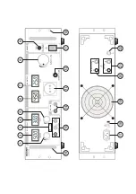
Page 18: ...wer switch for putting the device into operation I ON 0 OFF 12 Circuit breaker for AC output 13 Potential free AC socket no grounding contacts 14 Fixed voltage output 5VDC positive potential red negative potential blue 15 DC output adjustable plus pole red minus pole blue ground potential yellow green 16 Carrying handles 17 Grounded low power connection for mains cable 18 Input selector switch for...

Page 19: ...tested and meets the necessary European guidelines Grounding wire connection this screw may not be loosened Earth potential ground potential Electrical appliances and accessories are no toys and have no place in the hands of children On industrial sites the accident prevention regulations of the association of the industrial workers society for electrical equipment and utilities must be followed P...

Page 20: ...od of time or after it was exposed to extraordinary stress caused by transport You should also heed the additional safety instructions in each chapter of these operating instructions as well as in the operating instructions of the connected devices Functional Description The DC laboratory power unit is controlled linearly and shows very low residual ripple All DC outputs are isolated and feature a...

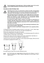
Page 21: ...e mains The displays remain on for a few seconds after it is switched off to unload the internal capacitators Always ensure a sufficient conductor cross section for the connection lines since overload may cause fire in the line Selecting the Grid Voltage The laboratory power unit can be operated with either 115 V or 230 V AC Before initial commissioning ensure that the rear mains voltage selection...

Page 22: ...e way to the left Connect the output socket and 15 with a connecting line at least 1 0 mm2 The output is short circuited The current value can be read in the display AMPERE The CC display is lit during setting Use the AMPERE rotary control 1 to adjust the max current current limitation After completing your settings remove the shorting bar The display shows the actual current for unlo aded output ...

Page 23: ... and short circuits In the AC area conductors and connection lines with protective isolation is manda tory at a voltage 50 V Ensure a sufficient cable diameter for the intended current The DC outputs on the power unit are present twice 15 and 20 or 14 and 21 respectively These out puts are connected and always have the same output voltage Remove any connected consumers from the output Switch on th...

Page 24: ...tistatic and dry cloth to clean the device Do not use any abrasive or che mical agents or detergents containing solvents Exchanging the Primary Fuse If it is no longer possible to switch on the laboratory power unit the primary mains fuse 9 is probably defective Proceed as follows to replace the mains fuse Switch off the power unit and remove all the connection cables and the mains plug from the d...

Page 25: ...e consumers Check the secondary fuse 12 at the AC output The CC 3 indicator is lit DC constant current operation The preset current was exceeded Check the power consumption of your consumer and if required increase the current limitation at the power unit The CV 3 indicator is lit Constant current operation The power unit works normally The set constant voltage is provided on the output Regularly ...

Page 26: ... 10 mV 3 mArms Control response at 100 5 mV 10 mV Load change 7 mA Control response at 3 mV 10 mV Mains fluctuation 5 mA Operating voltage 110 127 V AC 10 or 220 240 V AC 10 Power consumption 1500 W Mains fuse 115 V F15A250V fast blowing 5 x 20 mm 230 V F8A250V Operating temperature 0 to 40 C Rel air humidity 10 80 non condensing Safety class primary side 1 Mains Connection IEC 320 C14 Low power d...

Page 27: ... début d une coopération longue et efficace Nous vous souhaitons beaucoup de plaisir avec votre nouveau produit Voltcraft Table des matières Introduction 26 Contenu de la livraison 26 Utilisation conforme 27 Eléments de commande 28 Consignes de sécurité et avertissements 29 Description du fonctionnement 30 Mise en service 31 Sélection de la tension du réseau 31 Raccordement du cordon secteur 31 In...

Page 28: ...e défaut être transmi se aux autres appareils par le contact de conducteur de protection Danger de mort Evitez impérativement les câbles non isolés ou les contacts ouverts Risque de choc électrique en cas de contact entre deux câbles conducteurs Vous devez utiliser des câbles de raccordement suffisamment dimensionnés Une section de câble sous dimensionnée peut provoquer une surchauffe et un incend...

Page 29: ...acks 11 Commutateur principal de mise en service I marche 0 Arrêt 12 Automate de fusibles pour la sortie CA 13 Prise CA sans potentiel sans contact de conducteur de protection 14 Sortie de tension fixe 5 V DC potentiel positif rouge potentiel négatif bleu 15 Sortie CC réglable potentiel positif rouge potentiel négatif bleu potentiel de terre jaune vert 16 Poignées de transport 17 Raccordement de c...

Page 30: ...ur dans des locaux sec Cet appareil est homologué CE et répond aux directives nationales et européennes requi ses Raccordement du conducteur de protection Cette vis ne doit pas être desserrée Potentiel de terre potentiel de masse Les appareils électriques et les accessoires ne sont pas des jouets ne les laissez pas à la portée des enfants Dans les installations industrielles il convient d observer...

Page 31: ... appareil présente des dommages visibles l appareil ne fonctionne plus et l appareil a été stocké durant une période prolongée dans des conditions défavorables ou lorsqu il a subi de sévères contraintes liées au transport Respecter également les consignes de sécurité contenues dans les différents chapitres respective ment dans les notices d utilisation des appareils raccordés Description du foncti...

Page 32: ...utilisation de votre alimentation débranchez la du secteur Les afficha ges restent allumés quelques secondes après l arrêt pour décharger les condensa teurs internes Veillez impérativement à utiliser des câbles de raccordement de section suffisante une surcharge pouvant provoquer un incendie Sélection de la tension du réseau L alimentation peut fonctionner avec du 115 V ou du 230 V AC Assurez vous...

Page 33: ...es prises de sortie et 15 à l aide d un câble de liaison au moins 1 0 mm2 La sortie est alors court circuitée Vous pouvez lire la valeur de courant sur l écran AMPERE 2 L af fichage CC s allume pendant le réglage Vous pouvez régler le courant maximal limitation de courant à l aide du bouton tournant AMPERE 1 Une fois le réglage terminé enlevez le shunt de court circuit L écran affiche de nouveau l...

Page 34: ...t direct ou court cir cuit Dans la zone CA et à partir d une tension 50 V l utilisation de conducteurs et câbles de raccordement isolés est obligatoire Veillez à ce que la section du conducteur soit suffisante pour l intensité de courant prévue Sur l alimentation les sorties CC sont doublées 15 et 20 ainsi que 14 et 21 Ces sorties sont reliées entre elles et ont toujours la même tension de sortie ...

Page 35: ... propre sec antistatique et non pelu cheux sans produits corrosifs chimiques et contenant des solvants Remplacement du fusible de secteur primaire Si l alimentation de laboratoire ne peut plus être mise en service il est probable que le fusible de sec teur 9 soit défectueux Pour remplacer le fusible de secteur procédez comme suit Désactivez l alimentation et retirez tous les câbles de raccordement...

Page 36: ...ortie CA L indicateur CC 3 s allume Fonctionnement à courant constant CC L intensité de courant préréglée a été dépassée Contrôlez la consommation en courant de votre consommateur et augmentez le cas échéant la limitation de courant sur l alimen tation L indicateur CV 3 s allume Fonctionnement à tension constante L alimentation fonctionne normalement La tension constante réglée est donnée en sorti...

Page 37: ...mV 3 mArms Mode de régulation à 100 5 mV 10 mV Modification de charge 7 mA Mode de régulation à 3 mV 10 mV Variation de réseau 5 mA Tension de service 110 127 V CA 10 ou 220 240 V CA 10 Puissance absorbée 1500 W Fusible de secteur 115 V F15A250V Agile 5 x 20 mm 230 V F8A250V Température de service 0 à 40 C Humidité relative de l air 10 80 non condensant Classe de protection 1 côté primaire Raccord...

Page 38: ...ing Wij zijn ervan overtuigd uw keuze voor Voltcraft is tegelijkertijd het begin van een lange en prettige samenwerking Veel plezier met uw nieuwe Voltcraft product Inhoudsopgave Inleiding 37 Leveringsomvang 37 Voorgeschreven gebruik 38 Bedieningselementen 39 Veiligheidsvoorschriften en risico s 40 Functiebeschrijving 41 Ingebruikname 42 Keuze van de netspanning 42 Aansluiting van het netsnoer 42 ...

Page 39: ...ezien ingeval van fout evt de netspanning via de randaarde naar de andere apparaten kan worden overgedragen Levensgevaarlijk Niet geïsoleerde leidingen of open contacten moeten worden vermeden Er bestaat elektrocutiegevaar wanneer u twee spanningsvoerende leidingen aanraakt Er moeten voldoende gedimensioneerde aansluitkabels worden gebruikt Een te kleine geleiderdoorsnede kan tot oververhitting en...

Page 40: ...ningen voor reksystemen 11 Netschakelaar voor inbedrijfname I IN O UIT 12 Aardlekschakelaar voor AC uitgang 13 Potentiaalvrije AC contactdoos zonder randaarde 14 Voorgeschreven spanningsuitgang 5VDC pluspotentiaal rood minpotentiaal blauw 15 DC uitgang regelbaar pluspool rood minpool blauw aardpotentiaal geel groen 16 Draaggreep 17 Beschermcontact koude apparaataansluiting voor netsnoer 18 Ingangs...

Page 41: ... bij bijzondere tips of instructies voor de bediening Alleen voor gebruik in droge binnenruimtes Dit apparaat is CE goedgekeurd en voldoet aan de betrokken Europese richtlijnen Aardklem deze schroef mag niet losgedraaid worden Aardpotentiaal massapotentiaal Meetapparaten en accessoires zijn geen speelgoed houd deze buiten bereik van kinderen In industriële omgevingen dienen de Arbovoorschriften te...

Page 42: ...n veilig gebruik niet meer mogelijk is indien het apparaat zichtbaar is beschadigd het apparaat niet meer functioneert en het product gedurende langere tijd onder ongunstige omstandigheden is opgeslagen of het apparaat tijdens transport zwaar is belast Neem ook de veiligheidsvoorschriften in acht zoals die beschreven zijn in de afzonderlijke hoofdstuk ken resp in de gebruiksaanwijzingen van de aan...

Page 43: ...et als ze niet wordt gebruikt De indicatoren blijven na het uitschakelen nog enkele seconden ingeschakeld om de interne condensato ren te ontladen U moet bijzonder letten op een voldoende geleiderdoorsnede van de aansluitleidin gen aangezien overbelasting kan leiden tot leidingsbrand Keuze van de netspanning De laboratoriumvoeding kan naar keuze door 115 V of met 230 V AC worden aange dreven Wees ...

Page 44: ...bussen en 15 met een verbindingskabel minst 1 0 mm2 De uitgang wordt korgesloten Op het display AMPERE 2 kan de stroomwaarde worden afgelezen De indicator CC licht op tijdens de instelling Via de draairegelaar AMPERE 1 kan de max stroomsterkte stroombegrenzing worden ingesteld Verwijder de kortsluitbrug na het succesvol instellen Het display geeft weer de werkelijke stroom sterkte weer bij onbelas...

Page 45: ...act te voorkomen In het AC bereik is vanaf een spanning 50 V het gebruik van geïsoleerde leidingen en aansluitkabels voorgeschreven Let op een voldoende grote geleiderdoorsnede voor de geplande stroomsterkte De DC uitgangen zijn op de voeding dubbel voorhandne 15 en 20 en 14 en 21 Deze uitgangen zijn met elkaar verbonden en voeren altijd dezelfde uitgangsspanning Verwijder aangesloten verbruikers ...

Page 46: ...tistatische en pluisvrije reinigingsdoek zonder toevoeging van schurende chemische en oplosmiddelhoudende rei nigingsmiddelen Primaire netzekering vervangen Kan de laboratoriumvoeding niet meer ingeschakeld worden dan is de primaire netbeveiliging 9 waarschijnlijk defect Voor het vervangen van de netzekering gaat u als volgt te werk Schakel de netvoeding uit en verwijder alle aansluitsnoeren en st...

Page 47: ...kering 12 op de AC uitgang De CC indicator 3 brandt DC constante stroomgebruik De vooringestelde stroomsterkte werd overschreden Controleer de stroomopname op uw verbruiker en verhoog evt de stroombegrenzing op de voeding De CV indicator 3 brandt Gebruik bij constante spanning De voeding werkt normaal Op de uitgang wordt de ingestelde constante spanning uitgegeven Controleer regelmatig de technisc...

Page 48: ... Restspanningen 1 mVrms 10 mV 3 mArms Regelverhouding bij 100 5 mV 10 mV Lastverandering 7 mA Regeling bij 3 mV 10 mV Netschommeling 5 mA Voedingsspanning 110 127 V AC 10 of 220 240 V AC 10 Vermogensopname 1500 W Netzekering 115 V F15A250V Flink 5 x 20 mm 230 V F8A250V Bedrijfstemperatuur 0 tot 40 C Relatieve luchtvochtigheid 10 80 niet condenserend Beschermklasse primaire kant 1 Netaansluiting IE...

Page 49: ...48 ...

Page 50: ...49 ...

Reviews: