For measurement of AC currents proceed as follows:
1. Connect the red test lead to the V/Ohm socket and the black
test lead to the COM socket.
2. Set the rotary switch to "V~"; range-switching occurs automati-
cally, i.e. the measuring instrument matches itself automatically
to the measured value.
3. Connect the test probes to the object being measured (load,
circuit, etc.).
Each of the AC voltage ranges has an input impedance of
10 MOhm min. in parallel with < 20 pF (AC-coupled).
Notes!
Because the measurement input is very sensitive, it may be
that with unconnected test leads (not connected to a test cir-
cuit) random measured values can be displayed. This "manife-
station" is normal and disappears as soon as a measurement
is performed.
C Current measurement
To measure DC or AC currents, proceed as follows:
1. Connect the black test lead to the COM socket and the red test
lead to the mA socket; if you wish to measure currents up to
400 mA max. or via the 10A socket, if you wish to measure
currents between 400 mA and 10A max..
2. Set the rotary switch to the desired, required "A~" or "A=" mea-
suring range (400 µA or 4 mA 40 mA or 400 mA or 10A). With the
button "Select" you switch over from direct current to alternating
current and vice versa "~".
38
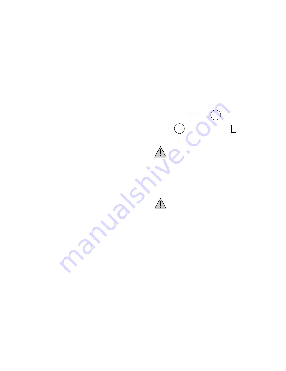
3. Connect the test probes to the object to be measured (see
following illustration).
Do not measure any currents in circuits in which
voltages greater than 250 V DC or V AC rms can
occur. Never measure currents over 10 A. Measure
only in circuits themselves fused at 10 A and in
which no power greater than 2500 VA can occur.
Measurements of currents at 10 A may only be of
10 seconds duration max. and may only be carried
out at intervals of 15 minutes (shunt cooling phase).
D Resistance measurement
Ensure that all circuit components, circuits and
assemblies and other objects to be measured are
completely voltage-free.
To record a measured value, proceed as follows:
1. Connect the black test lead with the COM socket and the red
test lead with the V/Ohm socket.
2. Position the rotary switch to "
Ω
"; range-switching occurs auto-
matically, i.e. the measuring instrument matches itself auto-
matically to the measured value.
3. Check the test leads for continuity by connecting both test
probes together. The indication should be 0.1 or 0.2 Ohm.
4. Now connect the measuring probes to the object to be
measured.
A
Fuse
Ammeter/
measuring device
Current-
source
Object under test,
consumer device
––
...
39


